Completion – Sub-Zero 427G User Manual
Page 9
subzero.com
|
9
MODEL 424G / 424FSG INSTALLATION
Completion
Plug the power cord into the grounded outlet, then slide
the unit into position. Verify the anti-tip bracket is properly
engaged.
It may be necessary to install the unit
1
/
4
"
(6)
beyond the
front surface of adjacent cabinetry, to prevent interference
when the door is opened to 145°. Refer to the full-scale
template on page 10.
HOME SECURITY CONNECTION
If the unit will be connected to a home security system,
make connections to the leads
shown in the illustration
below. Refer to the following color codes:
t
Normally open contacts—white with red stripe wire.
t
Normally closed contacts—white with blue stripe wire.
t
Common—gray with white stripe wire.
Use the spade terminals or wire nuts provided to make
proper wiring connections.
CAUTION
The alarm circuit in the unit is intended as a low-
voltage, low-current device only. It should not be used
to switch line power. Any unused terminals should be
completely insulated and all wires should be secured
away from conductive or moving components.
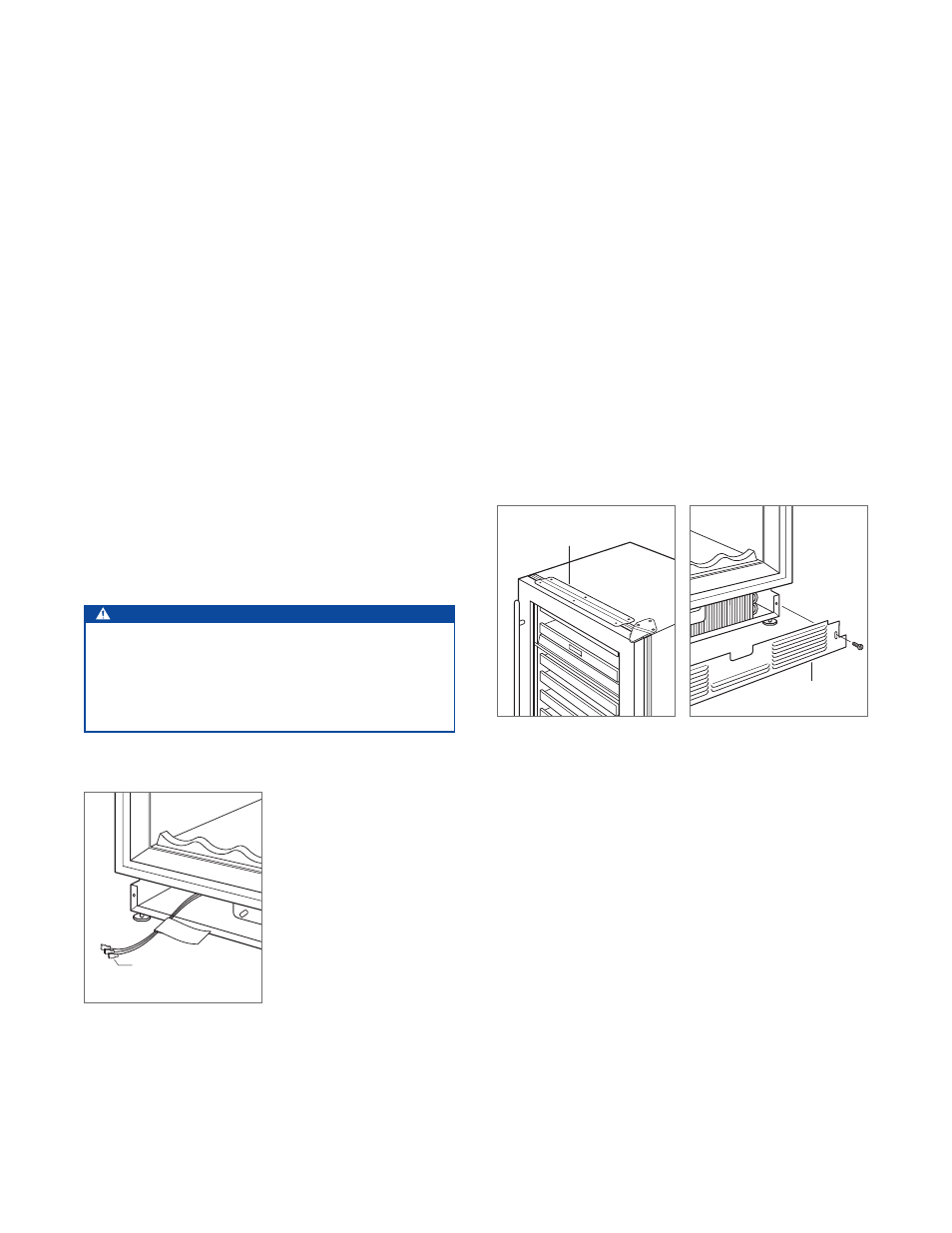
ANCHORING
To anchor, use the countertop bracket provided to secure
the unit to the underside of the countertop. Refer to the
illustration below. If the countertop bracket can not be
utilized, install shims along the top and sides of the unit.
KICKPLATE INSTALLATION
Install the kickplate using the two screws provided. Refer
to the illustration below. The kickplate must be removable
for service. The floor cannot interfere with removal. Do not
cover the louvered section of the kickplate.
COUNTERTOP
BRACKET
KICKPLATE
Anchoring.
Kickplate installation.
HOME SECURITY
LEADS
Home security connection.