Notice, Table parallelism – Woodstock SHOP FOX W1756 User Manual
Page 40
-38-
W1756/W1757 43" Wide-Belt Sander
SE
RV
IC
E
NOTICE
The table has been adjusted at the
factory and should require no further
attention. However, we recommend
verifying that it is parallel with the
sanding roller.
Table Parallelism
The corners of the table can be independently adjusted
up or down. By disconnecting the chain and turning the
pertinent table elevation screw sprocket (
Figure 39),
table parallelism can be achieved.
Adjusting the table parallelism can be a very tedious task
that takes a great amount of patience. DO NOT adjust the
table unless you have trouble sanding your workpiece to a
uniform thickness.
If a table adjustment is needed, take precise notes on the
positioning of the table elevation screws. This will allow
the original setting to be re-established.
To adjust the table parallelism, do these steps:
1. Pass a 43" wide board through the sander until the
entire surface of the board is making contact with
the sanding belt.
2. Measure the thickness of the board at various points
around the edge.
3. If there is a variation of thickness, the table can be
adjusted accordingly.
4. DISCONNECT THE SANDER FROM THE POWER SOURCE!
—
For minor adjustment, loosen the table mounting
bolts, shown in
Figure 40, and rotate the
elevation screw flange.
— For major adjustment, mark the chain location
on all sprockets, remove the chain from the
sprocket to be adjusted, and turn the sprocket
counterclockwise to raise the table. One quarter
of a turn raises or lowers an elevation screw
approximately 0.020".
5. Reinstall the chain onto the sprocket adjusted in
Step 4
, tighten the bolts, and test the machine.
NOTICE
When adjusting the left front elevation
screw, make the same adjustment to
the left rear elevation screw. This
ensures the height from the front to the
back of the table remains unchanged.
Do the same when adjusting the right
elevation screws.
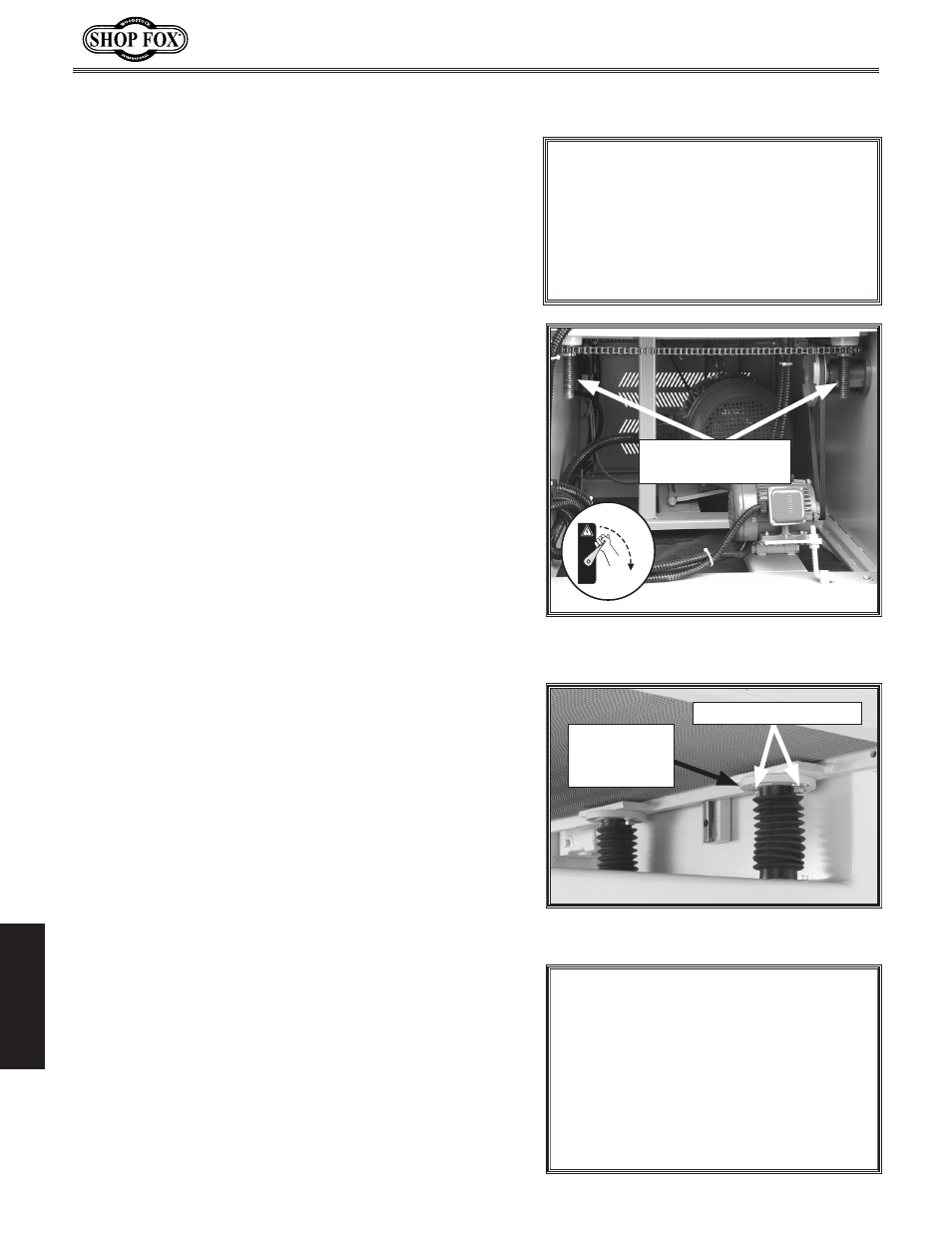
Figure
39
. View of elevation screw
sprockets.
OFF
Elevation Screw
Sprockets
Figure 40. Table mounting bolts and
elevation screw flange.
Elevation
Screw
Flange
Table Mounting Bolts