22 s, Ultra160 scsi connectors, Ide connectors – SUPER MICRO Computer SUPERSERVER 6012P-6 User Manual
Page 58
5-22
S
UPERSERVER 6012P-6 User’s Manual
Signal Names
+DB(12)
+DB(13)
+DB(14)
+DB(15)
+DB(P1)
+DB(0)
+DB(1)
+DB(2)
+DB(3)
+DB(4)
+DB(5)
+DB(6)
+DB(7)
+DB(P)
GROUN D
DIFFSENS
TERMPW R
TERMPW R
RESERVED
GROUN D
+ATN
GROUN D
+BSY
+ACK
+RST
+MSG
+SEL
+C/D
+REQ
+I/O
+DB(8)
+DB(9)
+DB(10)
+DB(11)
Connector
Contact
Number
1
2
3
4
5
6
7
8
9
10
11
12
13
14
15
16
17
18
19
20
21
22
23
24
25
26
27
28
29
30
31
32
33
34
Signal N ames
-DB(12)
-DB(13)
-DB(14)
-DB(15)
-DB(P1)
-DB(0)
-DB(1)
-DB(2)
-DB(3)
-DB(4)
-DB(5)
-DB(6)
-DB(7)
-DB(P)
GROU ND
GROU ND
TERMPW R
TERMPW R
RESER VED
GROU ND
-ATN
GROU ND
-BSY
-ACK
-RST
-MSG
-SEL
-C/D
-REQ
-I/O
-DB(8)
-DB(9)
-DB(10)
-DB(11)
Connector
Contact
Number
35
36
37
38
39
40
41
42
43
44
45
46
47
48
49
50
51
52
53
54
55
56
57
58
59
60
61
62
63
64
65
66
67
68
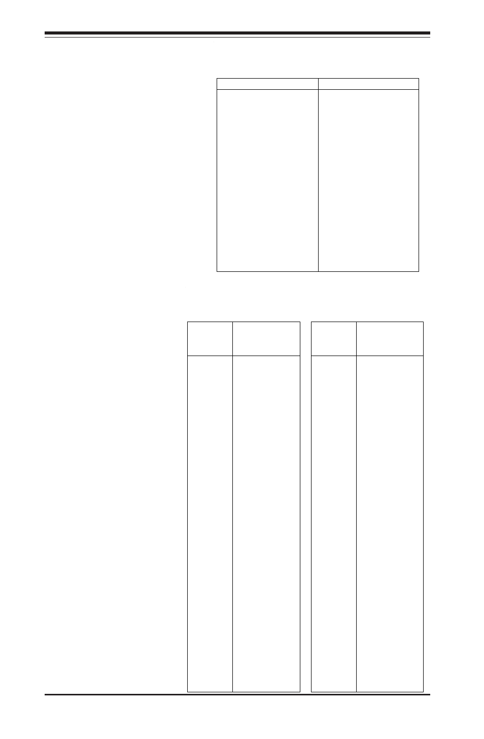
68-pin Ultra160 SCSI Connectors (JA1, JA2, JA4)
Ultra160 SCSI
Connectors
Refer to the table on
the right for the pin defi-
nitions of the Ultra160
S C S I c o n n e c t o r s l o -
cated at JA1 and JA2.
IDE Connectors
T h e r e a r e n o j u m p e r s t o
configure the onboard IDE#1
and #2 connectors (J2A and
J3A, respectively). See the
table on the right for pin
definitions.
Pin Number
Function
1
Reset IDE
3
Host Data 7
5
Host Data 6
7
Host Data 5
9
Host Data 4
11
Host Data 3
13
Host Data 2
15
Host Data 1
17
Host Data 0
19
GND
21
DRQ 3
23
I/O W rite-
25
I/O Read-
27
IOCHRDY
29
DACK3-
31
IRQ14
33
Addr 1
35
Addr 0
37
Chip Select 0
39
Activity
Pin Number
Function
2
G ND
4
Host Data 8
6
Host Data 9
8
Host Data 10
10
Host Data 11
12
Host Data 12
14
Host Data 13
16
Host Data 14
18
Host Data 15
20
Key
22
G ND
24
G ND
26
G ND
28
BALE
30
G ND
32
IOC S16-
34
G ND
36
Addr 2
38
Chip Select 1-
40
G ND
IDE Connector Pin Definitions
(J2A, J3A)