11 floppy/hard disk drive and scsi connections, Floppy connector, Chapter 5: advanced motherboard setup – SUPER MICRO Computer SUPERSERVER 6012P-6 User Manual
Page 57
Chapter 5: Advanced Motherboard Setup
5-21
5-11 Floppy/Hard Disk Drive and SCSI Connections
Note the following when connecting the floppy and hard disk drive cables:
•
The floppy disk drive cable has seven twisted wires.
•
A red mark on a wire typically designates the location of pin 1.
•
A single floppy disk drive ribbon cable has 34 wires and two connectors
to provide for two floppy disk drives. The connector with twisted wires
always connects to drive A, and the connector that does not have
twisted wires always connects to drive B.
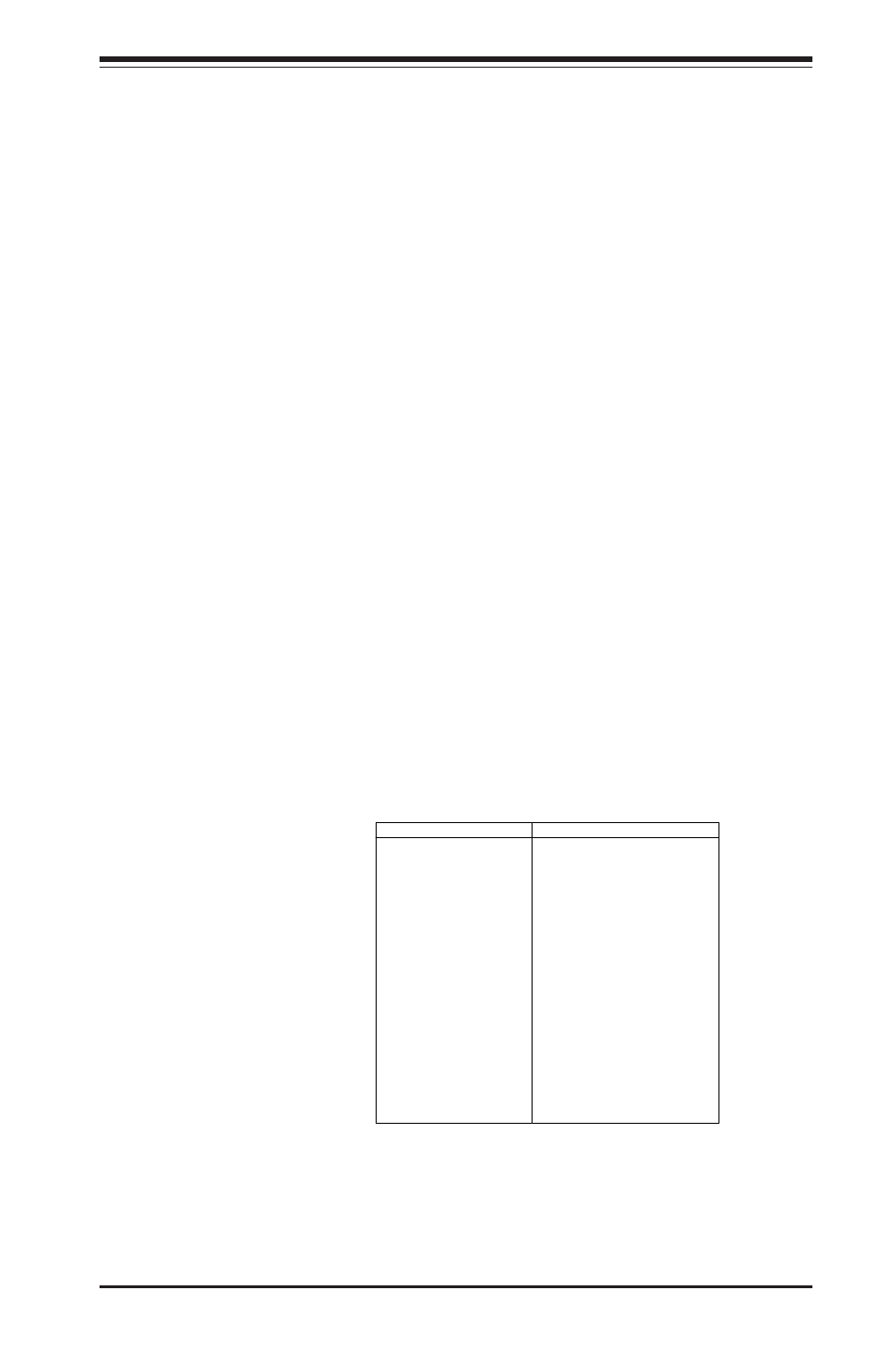
Pin Number
Function
1
G ND
3
G ND
5
Key
7
G ND
9
G ND
11
G ND
13
G ND
15
G ND
17
G ND
19
G ND
21
G ND
23
G ND
25
G ND
27
G ND
29
G ND
31
G ND
33
G ND
Pin Number
Function
2
FDHDIN
4
Reserved
6
FDEDIN
8
Index-
10
M otor Enable
12
D rive Select B-
14
D rive Select A-
16
M otor Enable
18
DIR-
20
STEP-
22
W rite Data-
24
W rite G ate-
26
Track 00-
28
W rite Protect-
30
Read Data-
32
Side 1 Select-
34
Diskette
Floppy Connector Pin Definitions (JP7)
Floppy Connector
The floppy connector is located
on JP7. See the table below for
pin definitions.