9 jumper settings, 17 cmos clear, Explanation of jumpers – SUPER MICRO Computer SUPERSERVER 6012P-6 User Manual
Page 53
Chapter 5: Advanced Motherboard Setup
5-17
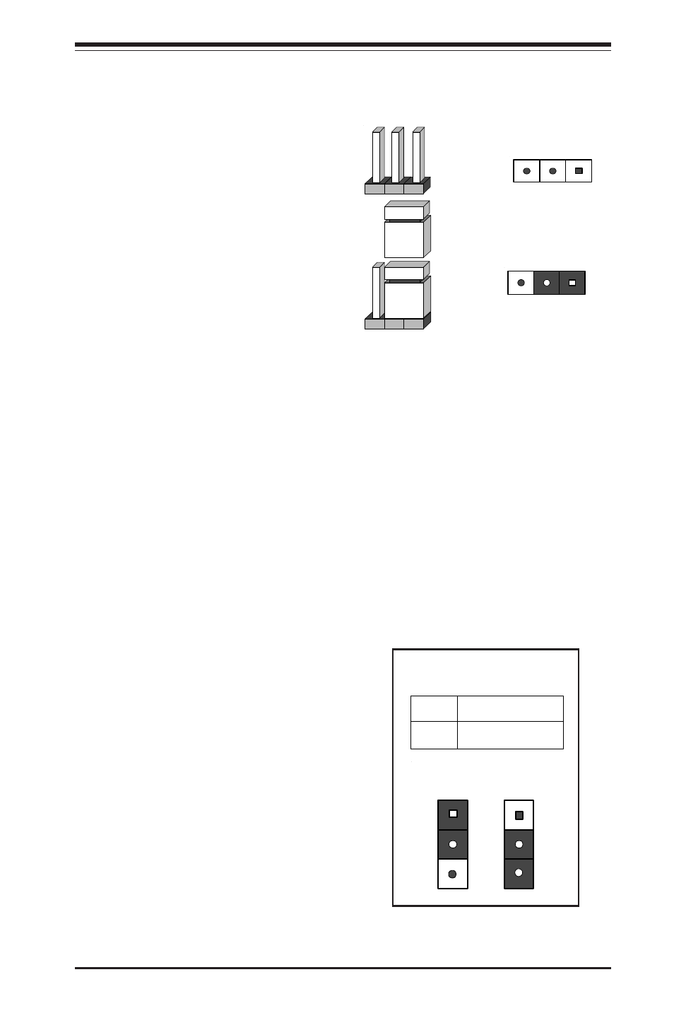
CMOS Clear
Refer to the table on the right for
the JBT1 jumper settings to clear
CMOS. Always remove the AC
power cord from the system be-
fore clearing CMOS.
Note: For an ATX power supply,
you must completely shut down
the system, remove the AC power
cord and then use JBT1 to clear
CMOS. Replace JBT1 back to the
pin 1-2 position before powering
up the system again. Do not use
the PW_ON connector to clear
CMOS.
CMO S Clear Jum per S ettings
(JBT 1)
Jumper
Position
1-2
2-3
Definition
Normal
CMO S Clear
Position
1-2
Position
2-3
Nor
m
al
CMO
S
Cl
ear
5-9
Jumper Settings
Explanation of
Jumpers
To modify the operation of the
motherboard, jumpers can be
u s e d t o c h o o s e b e t w e e n
o p t i o n a l s e t t i n g s . J u m p e r s
create shorts between two pins
to change the function of the
connector. Pin 1 is identified
w i t h a s q u a r e s o l d e r p a d o n
the printed circuit board. See
the motherboard layout page
for jumper locations.
N o t e : O n t w o p i n j u m p e r s ,
"Closed" means the jumper is
o n a n d " O p e n " m e a n s t h e
jumper is off the pins.
Connector
Pins
Jumper
Cap
Setting
Pin 1-2 short
3 2 1
3 2 1