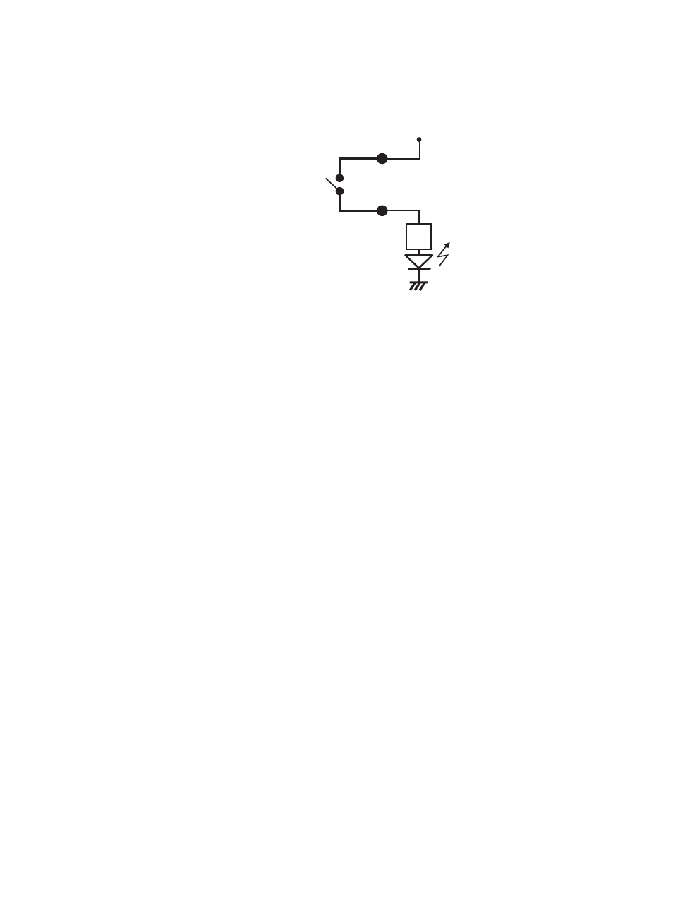
Wiring diagram for alarm output – Sony IPELA NSR-100 User Manual
Page 172
This manual is related to the following products:
See also other documents in the category Sony Video surveillance systems:
- DH180 (128 pages)
- SNC-DF80N/DF80P (2 pages)
- FCB-EX1010P (52 pages)
- SNC-xx (28 pages)
- SNC-CS50P (16 pages)
- SNC-CS50N (87 pages)
- SNC-CS3P (52 pages)
- EM100 (1 page)
- IPELA EXWAREPRO SNC-DM160 (2 pages)
- NTSC/PAL (44 pages)
- IPELA SNC-DH140/DH240 (2 pages)
- IPELA SNC-RZ25P (81 pages)
- FCB-EX1020 (67 pages)
- SNC-DH210 (97 pages)
- EXWAVEPRO SNC-CM120 (2 pages)
- SSC-MD33V (2 pages)
- CV-M300 (2 pages)
- SNC-DF Series (6 pages)
- DF70P (67 pages)
- IPELA SNC CH140 (2 pages)
- SSC-CD53V (2 pages)
- IPELA SNC-P1 (80 pages)
- SSC-MD53V (4 pages)
- CCTV Systems (75 pages)
- SNC-CM120 (2 pages)
- SNC-RZ25P (87 pages)
- FCB-EX980P (61 pages)
- SIR-4150 (20 pages)
- Network Video Monitoring (48 pages)
- SNC-DS10 (8 pages)
- IPELS SNT-EP154 (1 page)
- SSC-CD43VP (6 pages)
- SIR4260V (19 pages)
- SNC-P5 (79 pages)
- SNC-DM160 (2 pages)
- EVI-D100 (48 pages)
- IPELA SNC-DH180 (2 pages)
- SNC-DS60 (100 pages)
- Security Camera (204 pages)
- SCC-C7435 (5 pages)
- EVI-D100P (2 pages)
- SNC-VL10P (32 pages)
- IPELA SNC-RS46N (120 pages)
- CD-9255 (8 pages)