Sentry – Slant/Fin SENTRY SX-210 User Manual
Page 7
B. 1. This device must be installed after the boiler draft hood
(between the draft hood outlet and the connector to the out-
door chimney or vent) as close to the draft hood as practi-
cable, and without modification of the draft hood or the vent
damper. (See figures 1, 2 and 3.)
2. The inlet size of the vent damper must be the same nomi-
nal trade size as the outlet of the draft hood.
3. This device must be located in a venting system or section
of a venting system so that it serves only the single appli-
ance for which it is installed. (See figure 4.)
4. Clearances of not less than 6 inches (152MM) must be
maintained from combustible materials, with provisions for
service access.
C. NOW, PROCEED AS FOLLOWS:
Remove the cover from the aquastat control. Note the Molex
connector (MALE PLUG) inside the control box (see figure 6).
Remove knockout in the control housing marked for vent
damper, pass “Receptacle B” of vent damper harness through
the knockout and attach the flexible metallic connector to the
control housing with the nut. Join the two halves of the Molex
connector (MALE PLUG AND RECEPTACLE B). Replace the
control cover. Attach the other side of vent damper harness to
vent damper operator (if not attached) and connect Molex con-
nector to operator receptacle. (See figures 1 and 2.)
D. AFTER INSTALLATION:
1. Operate system through two complete cycles to check for
opening and closing in proper sequence, and proper burn-
er operation. DAMPER MUST BE IN OPEN POSITION
WHEN BOILER MAIN BURNERS ARE OPERATING.
2. Perform installation checks as required by ANSI specifica-
tion Z21.66. (See Vent Damper Instructions.)
3. Check the troubleshooting section if problems arise with the
installation.
E. THERMOSTAT HEAT ANTICIPATOR ADJUSTMENTS
If the 24V room thermostat that controls this boiler has an
adjustable heat anticipator and has previously been adjusted
without a vent damper, then see publication VD-40 for correct
electrical requirement adder for the vent damper used. If room
thermostat has not been adjusted, connect entire system to
thermostat and run the system while measuring the current
drawn through the thermostat wires. Set the heat anticipator
at the value of current measured. For more information, see
Slant/Fin vent damper installation manual, pub. VD-40, and the
manufacturer's vent damper booklet shipped with the vent
damper.
GAS PIPING—
A. Local installation codes apply. The pipe joint compound used
on threads must be resistant to the action of liquefied petro-
leum gases.
B. The gas supply line to the boiler should be run directly from
the meter for natural gas or from the fuel tank for L.P.
propane gas. See page 2 for location of union and manual
main shutoff valve that may be specified locally.
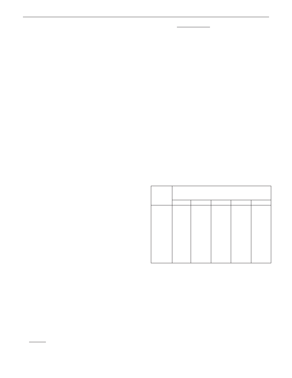
Selecting pipe size for natural gas:
1. Measure or estimate the length of piping from the meter
to the installation site.
2. Consult gas supplier for heating value of gas (Btu/cu. ft.).
3. Divide boiler rated input by heating value to find gas flow
in piping (cu. ft. per hour).
4. Use table A to select proper pipe size.
Example: Boiler model S-150 is to be installed. Distance
from gas meter to the boiler is 30 ft. Heating value of natur-
al gas is 1020 Btu/cu. ft. Select proper pipe size.
Gas flow = 150,000 Btu/hour = 147 cu. ft. per hour
1020 Btu/cu.ft.
At 30 ft. length of pipe, match required capacity from Table A
(choose higher capacity, in this case is 152 cu. ft. per hour).
Required pipe size is 3/4".
Improper gas pipe sizing will result in pilot flame outages,
insufficient heat and other installation difficulties. For more
information and also if other appliances are to be attached
to the piping system, see Appendix C of National Fuel Gas
Code ANSI Z223.1-latest edition.
C. The boiler and its gas connection must be leak tested before
placing the boiler in operation. Use liquid soap solution for
all gas leak testing. DO NOT use open flame.
This boiler and its individual shutoff valve must be discon-
nected from the gas supply piping system during any pres-
sure testing of that system at test pressures in excess of 1/2
PSIG.
This boiler must be isolated from the gas supply piping sys-
tem by closing its individual manual shutoff valve during any
pressure testing of the gas supply piping system at test
pressures equal to or less than 1/2 PSIG.
D. All gas piping used should be inspected thoroughly for
cleanliness before makeup. A sediment trap must be pro-
vided, as illustrated on page 2.
E. The minimum and maximum gas supply pressure (at the
inlet of gas valve) are shown on the boiler rating plate for the
type of gas used. Gas supply pressure should never be less
than minimum or more than maximum pressure when the
boiler or any other appliance is turned on or off.
1/2
3/4
1
1-1/4
1-1/2
10
132
278
520
1050
1600
20
92
190
350
730
1100
30
73
152
285
590
890
40
63
130
245
500
760
50
56
115
215
440
670
60
50
105
195
400
610
70
46
96
180
370
560
80
43
90
170
350
530
90
40
84
160
320
490
100
38
79
150
305
460
Length
of Pipe
in Feet
Gas Flow In Piping --
cu. ft. per hr.
Iron Pipe Size (IPS)—inches
At pressure drop of 0.3 in. water, specific gravity = 0.60.
7
Sentry
ELECTRICAL CONTROLS AND WIRING—
A. The electrical power to the boiler must be on a separately
fused and live circuit.
B. If an external electrical source is utilized, the boiler, when
installed, must be electrically grounded in accordance with
the requirements of the authority having jurisdiction or, in
absence of such requirements, with the National Electrical
Code, ANSI/NFPA No. 70-latest edition.
C. Basic control wiring diagrams are given on pages 14 and 15.
Other control systems may be factory supplied, see User's
Information Manual and Instructions packed with control
system supplied.
D. After placing the boiler in operation, the safety shutoff device
must be tested. See page 12 safety check.