4 experiment 4 - rpm drive mode rate controls, 1 general setup, 2 controlling the ramp rate – SMSC EMC2102 User Manual
Page 20: Figure 5.15 default ramp rate, Experiment 4 - rpm drive mode rate controls 5.4.1, General setup, Controlling the ramp rate
Fan Speed Control with the EMC2102 Device
Revision 0.2 (09-17-07)
USER MANUAL
SMSC EMC2102
20
5.4
Experiment 4 - RPM Drive Mode Rate Controls
This experiment is designed to gain familiarity with the rate control options available in the EMC2102
devices.
This experiment will discuss the effects of Maximum Fan Step and Update rate that can be used to
control the ramp rate of a fan. The two parameters ensure the fan reaches the desired drive in a
reasonable time with no oscillations.
The CMF file for this experiment is the same as for Experiment 1, EMC1202_default.cmf.
5.4.1
General Setup
For all these tests, the Fan Drive Setting register (51h) and the TACH Reading registers (58h) are
selected to plot. As bits are switched in each of the tests, the register name and address will be
provided.
5.4.2
Controlling the Ramp Rate
Controlling the ramp rate can improve the performance of the fan control loop by limiting the slew rate
of the fan drive. The EMC2102 uses the UPDATE bits in the FAN Configuration register (52h, bits [2:0])
to determine the time interval between two updates of the controller output, and uses the FAN Step
register (54h) to determine the maximum allowed hexadecimal count (STEP) of the output (Refer to
Figure 5.11 "Fan Control Parameters"
for more details). These two parameters can only work in the
RPM control mode. When the RPM control function is disabled (52h[7]= 0), any change in the Fan
Drive Setting register (51h) will immediately change the output.
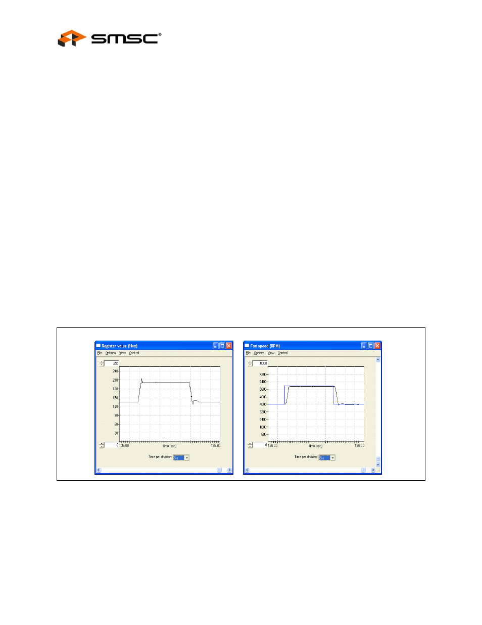
Figure 5.15, "Default Ramp Rate"
illustrate the drive and response with the default
UPDATE (400ms) and default STEP SIZE (Max. 16 drive settings per update), while changing the fan
target speed from 4000 rpm to 6000rpm.
The ramping rate in this mode can be accelerated or slowed down, depending on application and the
values of register 52h (UPDATE) and 54h (STEP SIZE). In the next experiment (
Step Size with Different UPDATE Settings"
), the default STEP SIZE with different UPDATE (400 ms
and 100 ms) were used, The 100 ms setting has the effect of speeding the loop up by a factor of 4,
as that is the ratio between minimum (100ms) and default (400ms) UPDATE settings.
Figure 5.15 Default Ramp Rate