Figure 5.7 plot windows, Figure 5.8 plot examples, 2 experiment 2 - rpm based closed-loop fan control – SMSC EMC2102 User Manual
Page 13: 1 getting started, Getting started, Figure 5.8 plot examples figure 5.7 plot windows, Figure 5.7, "plot windows, User manual
Fan Speed Control with the EMC2102 Device
SMSC EMC2102
USER MANUAL
Revision 0.2 (09-17-07)
13
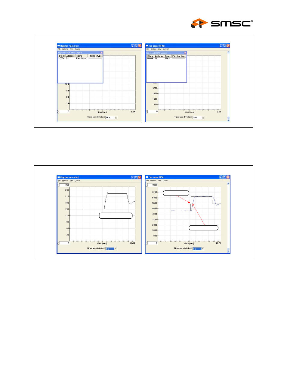
The two plots shown in
are in sync. If the scaled data is desired for
analysis or archival, the data may be stored in a semi-colon separated text file from each of the plot
windows. Simply select File Export, and enter a filename in the Save window.
5.2
Experiment 2 - RPM Based Closed-Loop Fan Control
The experiment 2 is designed to gain familiarity with the closed-loop RPM controller implemented in
the EMC2102. This experiment will discuss the effects of gain, spin-up, and minimum settings on the
closed-loop performance.
The cmf file for this experiment is EMC2102_RPM.cmf.
5.2.1
Getting Started
For all these tests, the Fan Drive Setting register (51h), the TACH Target register (57h) and the TACH
Reading registers (58h) are selected to plot. As bits are switched in each of the tests, the register name
and address will be provided.
Figure 5.7 Plot Windows
Figure 5.8 Plot Examples
TACH Target (57h)
Fan Driver Setting (51h)
TACH Reading (58h)