Cooling system, Chapter 1: introduction – SUPER MICRO Computer SUPERSERVER 6015B-T User Manual
Page 15
Chapter 1: Introduction
1-5
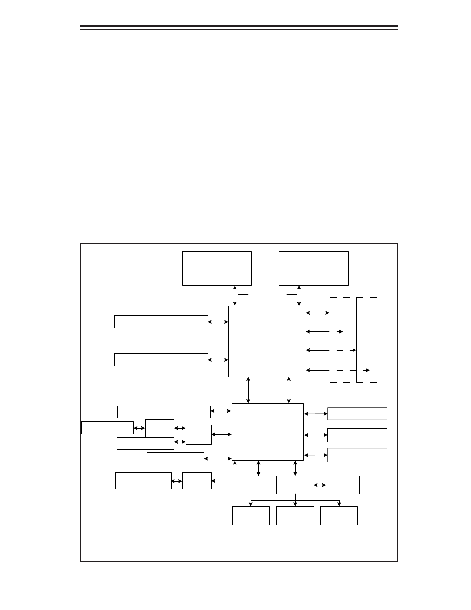
Figure 1-1. Intel 5000P/ESB2 Chipset:
System Block Diagram
Note: This is a general block diagram. Please see Chapter 5 for details.
ESB2
CPU1
FB
D
D
IM
M
B
a
n
k
1
DDR2
1067/1333 MT/s
SATA Ports (6)
IDE Ports (2)
USB Ports (5)
S I/O
BIOS
Kybd/
Mouse
Floppy
COM
Ports (2)
CPU2
5000P
MCH
Slot 6: PCI-Exp x8/SEPC
Slot 5: PCI-Express x8
LPC
82563
ATI
ES1000
FB
D
D
IM
M
B
a
n
k
2
FB
D
D
IM
M
B
a
n
k
3
FB
D
D
IM
M
B
a
n
k
4
FBD CH0
FBD CH1
FBD CH2
FBD CH3
PC
I-
E x
4
PC
I-
E x
8
Slot 4: PCI-Express x8
PXH
Slot 2: PCI-X
Slot 1: PCI-X
Slot 3: PCI-X
LAN Ports (2)
USB 2.0
3.0 Gb/s
ATA 100
PCI 32
PCI-X 133
PCI-Exp
x8
PCI-Exp
x4
Kumeran
PCI- Exp
x8
PCI- Exp
x8
AIC
7902
Cooling System
The SC815TQ-700/SC815S-700 chassis' revolutionary cooling design has
been optimized to provide suffi cient cooling for dual Xeon confi gurations. The
SC815TQ-700/SC815S-700 includes four heavy duty 40-mm counter-rotating
blower fans located in the middle of the chassis. In the event of a fan failure, the
ambient air temperature inside the chassis will rise and activate an overheat LED
(fan speed is controlled by the system temperature).