Notice – Woodstock SHOP FOX M1102 User Manual
Page 15
-13-
M1102/M1103 16-Speed Drill Press
SE
T
U
P
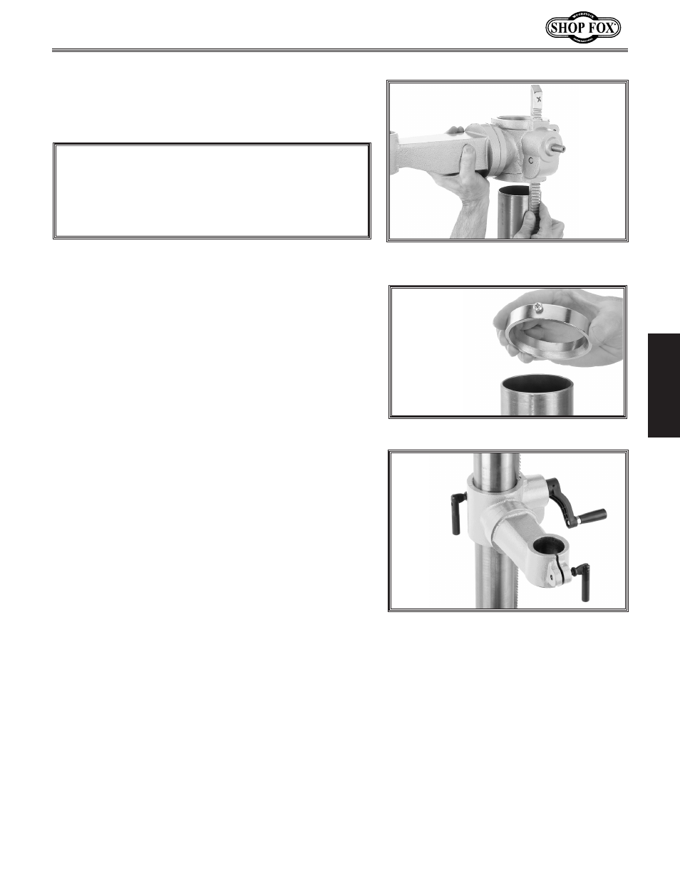
Figure 6. Sliding table support and rack
over the column.
Figure 7. Correct column ring orientation.
Figure 8. Handles and lock levers
installed.
4. Place the rack inside of the table support assembly,
mesh it together with the pinion, and slide the table
support/rack assembly over the column, as shown in
Figure 6.
5. Slide the column ring over the column with the bev-
eled edge facing down (
Figure 7), fit the beveled
edge of the column ring over the rack, and tighten
the column ring lock screw.
Note: Make sure the rack is seated firmly in the
lower ring.
6. Install the crank handle over the pinion shaft, and
tighten the setscrew in the crank handle against the
flat part of the pinion shaft.
Note: If the crank handle does not slide all the way
onto the pinion shaft, loosen the setscrew, and
gently tap the handle with a rubber hammer.
7. Thread the handle into the crank handle.
8. Thread the large lock lever into the back of the
table support assembly approximately three turns,
for now.
Note: The lock levers must be installed from the
non-threaded shaft sides on the table support
assembly to function correctly.
9. Thread the small lock lever into the front part of
the table support assembly approximately three
turns, for now. The assembly should now be assem-
bled as shown in
Figure 8.
NOTICE
DO NOT overtighten the column ring lock screw
in the next step, or you will split the column ring.
Merely tighten it to a snug fit.