Ata registers – Seagate STT8000A User Manual
Page 40
Chapter 5
ATAPI Interface
Page 32
STT8000A Product Manual
ATA registers
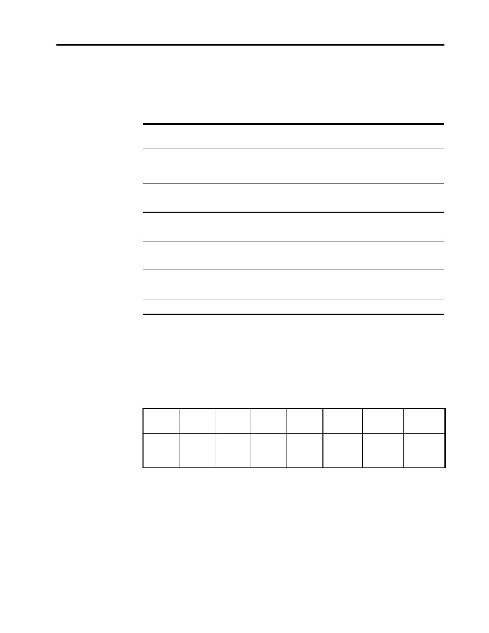
The following table lists the values for the registers during register initialization.
Register
POR
RESET–
(Hard Reset)
ATA Reset
(SRST Bit)
ATAPI Soft
Reset
Read/Identify
Device Cmds
STATUS
00h
00h
00h
10h
41h
(DRDY+ERR)
ERROR
01h
(No
Error)
01h
01h
01h
04h
(ABRT)
Sector Count
(ATAPI Intr.
Reason)
01h
01h
01h
01h
—
Sector Num.
(ATAPI
Reserved)
01h
01h
01h
01h
—
Cylinder Low
(ATAPI Byte
Count High)
14h
14h
14h
14h
14h
Cylinder High
(ATAPI Byte
Count High)
EBh
EBh
EBh
EBh
EBh
Drive/Head
00
00
00
—
—
During an ATA soft reset or aborted ATA command, the host view of the DSC bit (Status
register) will be cleared, along with the DRDY bit. Any ATAPI command including ATAPI
Identify) can be used to set DRDY true and to re-enable host view of DSC bit.
Status Register
The following layout represents the Status Register. The CORR and IDX bits are not
used by the drive.
7
6
5
4
3
2
1
0
BSY
DRDY
-
(0)
DSC
DRQ
CORR
(0)
IDX
(0)
CHECK
Bit
Mnemonic
Description
7
BSY
Busy—set when only drive has access to ATA registers.
6
DRDY
Drive Ready—set when DSC is valid.
4
DSC
Drive Seek Complete—set when drive ready for command.
3
DRQ
Data Request—set when data ready to be transferred.
0
CHECK
Check—set when an error has occurred.