Setting jumpers, Figure 3-1 location of jumper block and connectors, Figure 3-2 jumper block and jumper settings – Seagate STT8000A User Manual
Page 24
Chapter 3
Installation
Page 16
STT8000A Product Manual
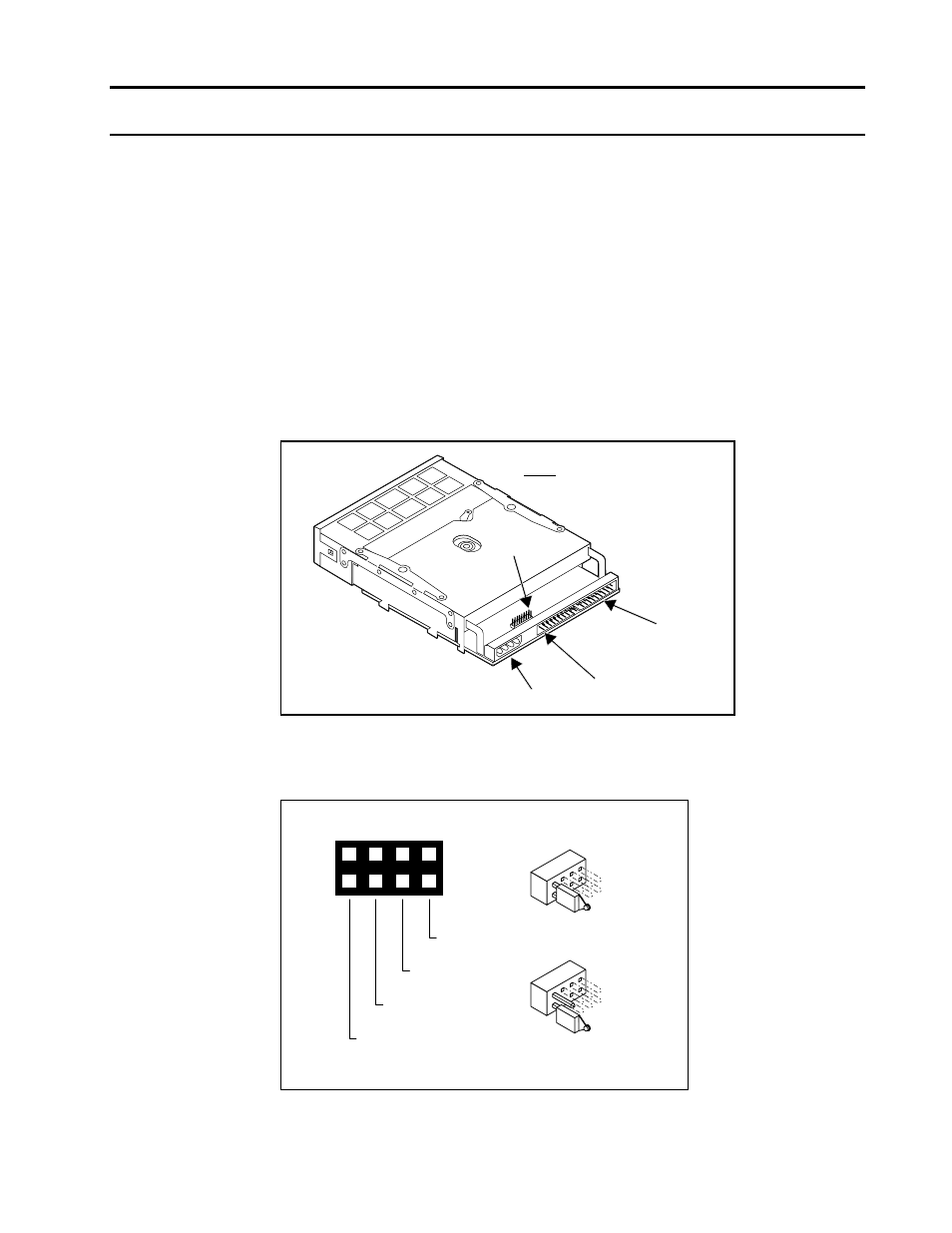
Setting jumpers
Review the jumper settings to ensure that the jumpers are properly configured for
your system. Figure 3-1 shows the location of the jumper block. Figure 3-2 shows
the jumper block.
Note:
Record your jumper settings prior to installation. They are not visible after
the drive has been installed.
The default setting is Slave mode with a jumper over pin 3 and pin 4.
Your system setting may vary, so be sure to check your computer or ATAPI
controller manual to determine the proper configuration choice for your system.
Figure 3-1
Location of jumper block and connectors
IDE
CONNECTOR
IDE PIN 1
POWER
CONNECTOR
NOTE:
Bottom of drive shown.
JUMPER
BLOCK
PIN 1
Figure 3-2
Jumper block and jumper settings
6
4
3
2
1
8
NOT USED
MASTER
SLAVE
CABLE SELECT
JUMPER ON
JUMPER OFF
7
5
(TOP OF TAPE DRIVE)
- Barracuda ST3200826A (48 pages)
- BARRACUDA ST3120023AS (2 pages)
- BARRACUDA ST3750840AS (68 pages)
- 1270SL (40 pages)
- BARRACUDA ST1181677LW (2 pages)
- Barracuda ST3750640NS (2 pages)
- BARRACUDA ST3500641AS (2 pages)
- BARRACUDA XT SERIES SATA ST32000641AS (42 pages)
- SV35.3 Series Serial ATA ST31000340SV (54 pages)
- BARRACUDA ST31500341AS (50 pages)
- BARRACUDA ST3750525AS (48 pages)
- Cheetah 15K.5 SAS ST3300655SS (86 pages)
- BARRACUDA 7200.11 SERIAL ATA ST3500620AS (48 pages)
- U4 ST32112A (42 pages)
- BARRACUDA ST3400632AS (50 pages)
- BARRACUDA ST3160316AS (48 pages)
- BARRACUDA ST31000640SS (82 pages)
- U8TM FAMILY ST317221A (2 pages)
- U10TM ST315323A (2 pages)
- BlackArmor WS 110 (2 pages)
- Barracuda ST3160023A (52 pages)
- CONSTELLATION ES SERIAL ATA ST32000644NS (48 pages)
- BARRACUDA ST360021A (2 pages)
- U Series 9 ST380012A (2 pages)
- BARRACUDA ST3320613AS (48 pages)
- DB35 Serial ATA ST3400832SCE (44 pages)
- Barracuda ST340015A (58 pages)
- Ultra 160 (186 pages)
- Barracuda ST31000640FC (84 pages)
- ST3320310CS (50 pages)
- BARRACUDA ATA FAMILY ST328040A (42 pages)
- BARRACUDA ST3160318AS (48 pages)
- Barracuda ST380219AS (2 pages)
- Barracuda ST340211AS (2 pages)
- SV35 SERIES ST3160812SV (62 pages)
- SV35.4 (44 pages)
- ST973401LC (1 page)
- BARRACUDA ES SERIAL ATA ST3250620NS (54 pages)
- BARRACUDA ST3500820AS (46 pages)
- Barracuda ST380811AS (50 pages)
- SV35.5 SERIES SATA ST3250311SV (46 pages)
- Barracuda ST1181677FC (2 pages)
- Barracuda ST3160827AS (54 pages)
- BARRACUDA 7200.10 SERIAL ATA ST3250410AS (44 pages)
- DB35 Serial ATA ST3200826SCE (50 pages)