Soundscape mixpander – Solid State Logic Soundscape Mixer User Manual
Page 65
Soundscape Mixpander
Page 65 of 109
Graphical display
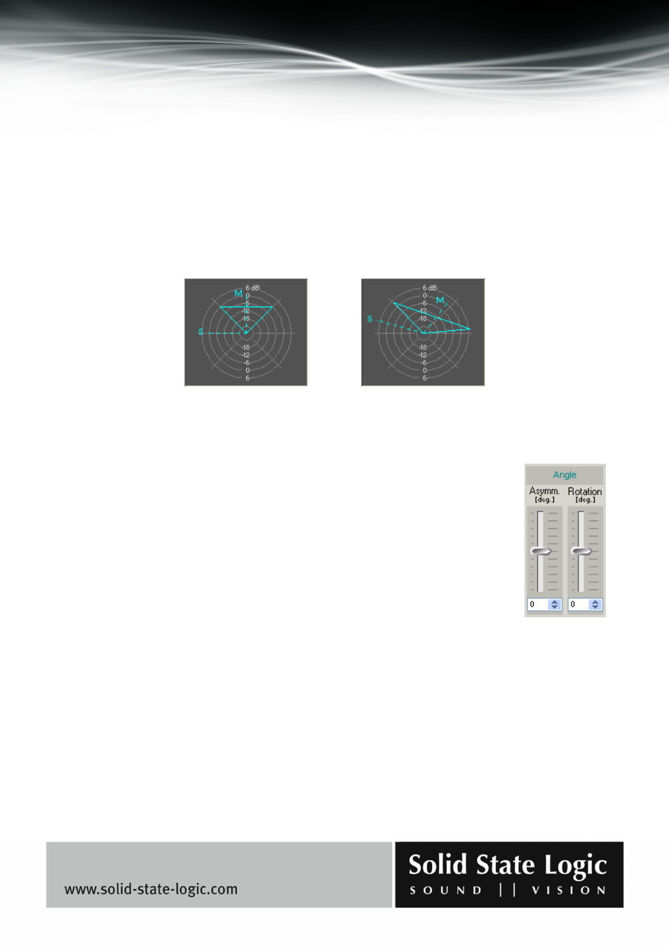
The display provides a visual representation of the perceived soundfield, as defined and modified
in real time by the parameter controls, and contributes to the intuitive operation of the MS
Decoder. The direction and length of the M and S vectors (dotted lines) represent the orientation
and gain of the mid signal microphone and side signal microphone respectively. The extent of the
triangle (solid lines) in relation to the dB scale represents the overall gain, the angle between the M
and S vectors varies according to the asymmetry parameter setting, and the overall orientation of
the displayed soundfield responds to adjustments of the rotation and asymmetry parameter
settings.
Angle Section
– Asymmetry (-90, 90 degrees):
Angle shift applied to the side MS matrix input signal along with the angle shift
introduced due to the “rotation” parameter. The value of the parameter has no
effect if the MS matrix is not active.
NOTE: The setting of this parameter does not affect the mid MS matrix input
signal at all.
– Rotation (-45, 45 degrees):
Angle shift applied to both the side and mid MS matrix input signals.
NOTE: The angle shift of the side MS matrix input signal also depends on the setting of the
asymmetry parameter.