Component/rgb input connection, Connections, Component signals (y, p – JVC GD-V501PCE User Manual
Page 37: Connection, Rgb signal (r, g, b, hd, vd) connection
37
Connections
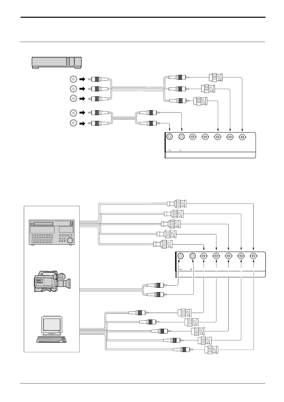
Component/RGB Input connection
Notes:
(1) Change the “Component/RGB-in” setting in the “Setup” menu to “Component”. (see page 30)
(2) Additional equipment, cables and adaptor plugs shown are not supplied with this set.
Component signals (Y, P
B
, P
R
) connection
Notes:
(1) Change the “Component/RGB-in” setting in the “Setup” menu to “RGB”. (see page 30)
(2) Additional equipment, cables and adaptor plugs shown are not supplied with this set.
RGB signal (R, G, B, HD, VD) connection
Audio input to
L/R sockets
G
B
R
VD
HD
AUDIO
2
×
RCA audio cables
5
×
BNC
RGB cables
RCA-BNC
adaptor-plug
RGB input to
R, G, B, HD, VD
sockets
Example of input signal source
HDTV-compatible VCR
Computer
RGB camera
R
L
AUDIO
VD
HD
P
R
/C
R
/R
P
B
/C
B
/B
Y/G
COMPONENT/RGB IN
R
L
Y
P
B
P
R
AUDIO
3
×
RCA
video cables
2
×
RCA
audio cables
(DVD Player)
Y, P
B
, P
R
P
R
/C
R
/R
P
B
/C
B
/B
Y/G
COMPONENT/RGB IN
VD
HD
R
L
AUDIO
RCA-BNC
adaptor plug