Controls, connectors and indicators – JVC VN-C655U User Manual
Page 10
10
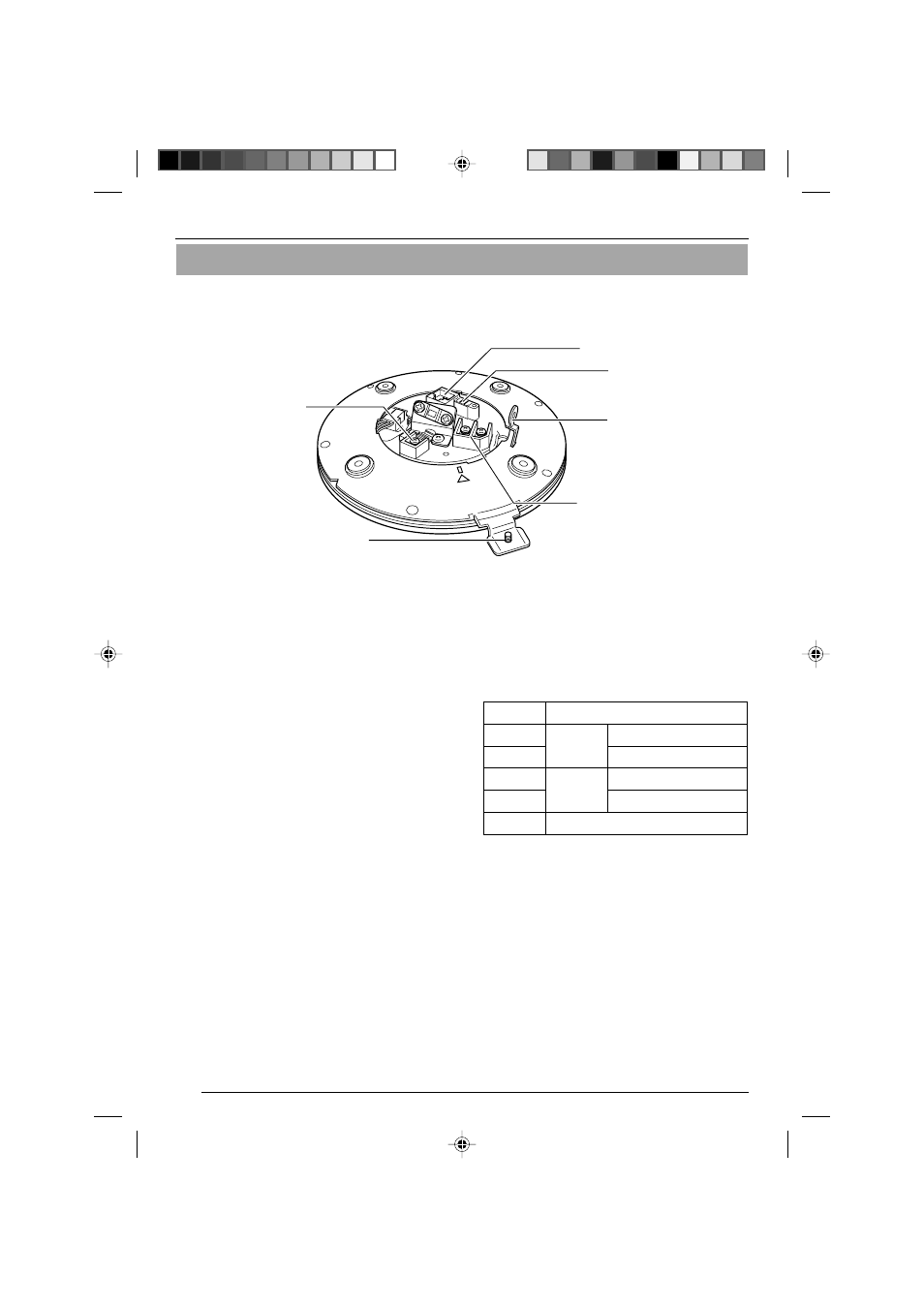
Controls, Connectors and Indicators
Ⅵ Ceiling Mount
1
[MONITOR OUT] Coaxial Cable Terminal
Output Terminal of a composite video signal
(1 Vp-p) with an output impedance of 75 Ø, to
be connected to video monitor, etc.
(
☞
Page 16)
2
Locking Screw
Tighten this screw to fasten the camera clamp-
ing bracket.
3
[POWER INPUT DC18V] Terminal
Connect to a supplied AC adaptor.
4
Safety Wire Hole
To prevent the possibility of the entire camera
falling down, attach the safety wire between
this hole and a secure attaching position in
the ceiling.
5
[ALARM I/O]Alarm Input/Output Terminals
Terminals for Alarm input and Alarm output.
(
☞
Page 18)
6
[10BASE-T/100BASE-TX] Connector
For network connection with a LAN cable
(
☞
Page 17)
Pin No.
Signal Name
1
ALM OUT 1
2
ALM OUT 2
3
ALM IN 1
ALARM
OUT
ALARM
IN
4
ALM IN 2
5
GND
6
5
4
3
2
1
Introduction
VN-C655(reed me)_p2-29
04.9.22, 8:18 PM
10
- GR-D295U (56 pages)
- GR-DVL25 (64 pages)
- TK-C921 (2 pages)
- CompactFlash LYT0143-001A (68 pages)
- KY-F70B (221 pages)
- GR-D248 (52 pages)
- LYT1366-001A (80 pages)
- GR- (2 pages)
- GR-DVL155 (68 pages)
- GR-DVL522 (88 pages)
- KY-F75 (52 pages)
- TK-C721 (2 pages)
- GR-DVL315 (68 pages)
- Digital Video Camera GR-DX78 (52 pages)
- GC-QX3 (96 pages)
- GR-D395U (112 pages)
- GC-S5 (100 pages)
- GR-DVX4 (80 pages)
- VN-C30U (32 pages)
- GR-D371U (112 pages)
- GR-AX937 (55 pages)
- GC-QX3HD (104 pages)
- GR-D770U (48 pages)
- 0810YMH-AL-OT (54 pages)
- DVL367 (88 pages)
- GR-D280 (56 pages)
- TK-WD310 (12 pages)
- KY-F1030 (26 pages)
- GR-DF540 (68 pages)
- GR-DF565 (68 pages)
- GR-DVL1020 (88 pages)
- GZ-MC500 (7 pages)
- GR-DV801 (88 pages)
- GR-DVJ70 (72 pages)
- DVL522U (38 pages)
- GR-D650E (56 pages)
- GR-D22 (40 pages)
- GR-X5EE (64 pages)
- Digital Video Camera GR-DVL105 (72 pages)
- GR-DLS1 (88 pages)
- GR-D350EW (44 pages)
- GR-D750US (40 pages)
- GZ-MC100US (44 pages)
- GR-DVX PRO (84 pages)
- GC X 1 (92 pages)