JVC DT-V24L1 User Manual
Page 7
7
1
Display the menu.
To display the main menu
\ Press MENU button.
To display the set-up menu
\ Press button while pressing button.
2
Press buttons to select an item,
then press button.
3
Press buttons to select an item,
then press buttons to make
adjustments.
4
Press MENU button to return to the
previous menu.
• Pressing the button again finishes the menu
operation.
NOTE
For some items, adjustments will be made by pressing
in step 2 .
Menu Operations
Select audio channels of EMBEDDED AUDIO
signals to output from the speakers (L/R) and
MONITOR OUT (L/R) terminals.
1
Press or button to display the
screen for audio channel selection.
You cannot display this screen when displaying
a menu screen.
2
Press buttons to select the left
(L) or right (R).
3
Press buttons to select an
audio channel.
NOTE
• You can select channels from 12 audio channels.
• You have to choose a group of selectable audio
channels before the channel selection (☞ “E.AUDIO
GROUP” on page 11).
4
Press MENU button to finish the
audio channel selection.
Audio Channel Selection
(DT-V24L1D and DT-V20L1D only)
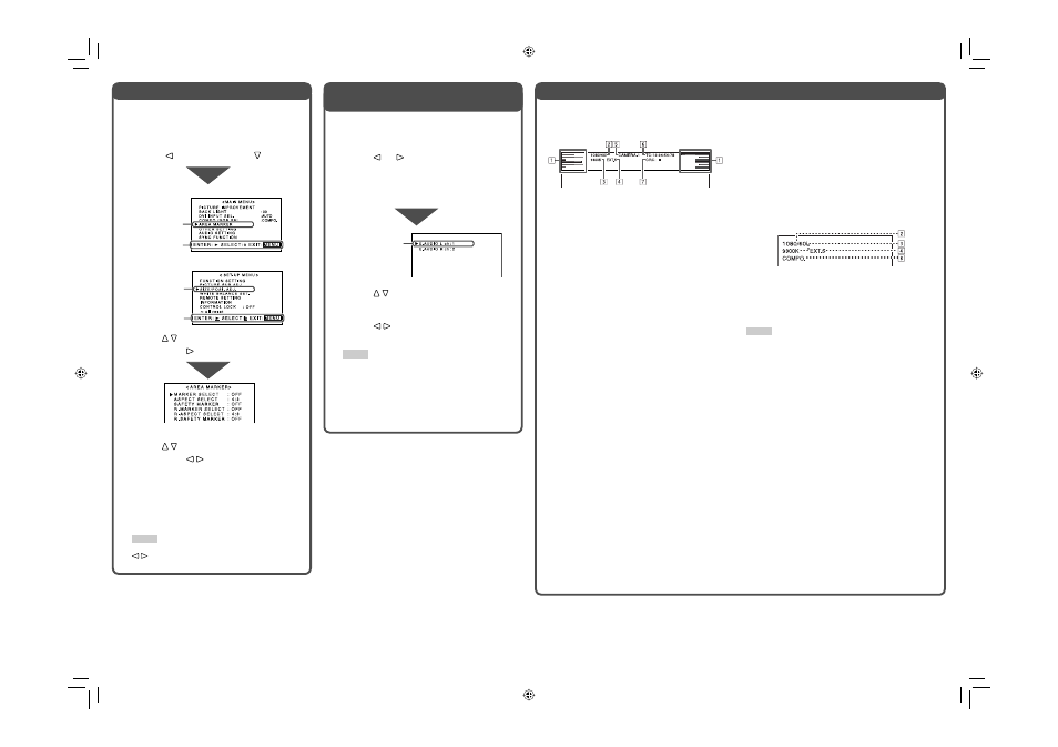
About the Status Display
When the main menu is displayed
When the set-up menu is displayed
Selected item
Selected item
Operation guide
Operation guide
Ex.: When “AREA MARKER” is selected
Selected item
The monitor displays the status information below
depending on the settings of the menu and buttons at
the top of the screen.
1
Audio level meter*
• Not displayed when no EMBEDDED AUDIO
signal is input or “LEVEL METER ch” is set to
“OFF” (☞ “AUDIO SETTING” on page 11).
2
Signal format
• “*” is displayed at the end of the indication when
a DVI-D signal protected with HDCP is input.
• “NO SYNC” is displayed when no video signal is
input.
• “Out of range” is displayed for a noncompliant
video signal input. When “COLOR SYSTEM” is
set to “AUTO” (☞ “OTHER SETTING” on page
11) and the noncompliant video signal is a
composite one, “OTHERS” is displayed.
3
Setting of “COLOR TEMP.”
☞ “WHITE BALANCE SET.” on page 12
• “*” is displayed at the end of the indication when
“9300K” or “6500K” is selected in “COLOR
TEMP.” and its drive levels or cutoff points are
adjusted.
4
Displayed when “SYNC INPUT SEL.” is set to
“EXT.” (external synchronization)
☞ “ SYNC FUNCTION” on page 11
5
Source name entered in “CHARACTER SET.”
☞ “INFORMATION” on page 13
• Displayed when “MONITOR NAME” is set to
“ON” (☞ “INFORMATION” on page 13).
• Displayed in large letters when “STATUS
DISPLAY” is set to “OFF” or “AUTO” (☞
“INFORMATION” on page 13).
6
Time code*
☞ “
u
T.C. (time code) button/lamp” on page 6
• When the input signal includes no time code,
“TC:
– –
:
– –
:
– –
:
– –
” is displayed.
7
CRC error indication*
☞ “CRC ERROR” in “INFORMATION” on page 13
• A red square is displayed when an error occurs.
* DT-V24L1D and DT-V20L1D only
If you press INPUT SELECT button of the current
input, the information below (
2
–
4
and
8
) is
displayed in large letters for about three seconds.
Then the status information on the left column
(
1
–
7
) is displayed.
When “STATUS DISPLAY” is set to “AUTO” or “ON,”
the information below is also displayed in the cases
below (☞ “INFORMATION” on page 13).
• When you change the input
• When the signal condition of the current input
changes
• When turn on the monitor
8
Setting of “COMPO./RGB SEL.” or the signal
form of DVI input
☞ “COMPO./RGB SEL.” or “DVI INPUT SEL.” on
page 10
NOTE
• When “STATUS DISPLAY” is set to “OFF” or “AUTO” (☞
“INFORMATION” on page 13), 2 – 4 are not displayed at
the top of the screen.
• While displaying any of the status indications except 6 at
the top of the screen, the picture is displayed below the
status display area. (The status display may overlap with
the picture when a computer signal is input.)
DT-V2420L1D_UA_R.indd 7
DT-V2420L1D_UA_R.indd 7
06.11.17 10:40:15 AM
06.11.17 10:40:15 AM