External control, 7 using the make/trigger system, 7 about the external control – JVC DT-V24L1 User Manual
Page 14
14
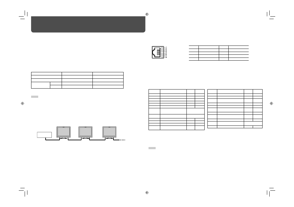
7 Using the MAKE/TRIGGER system
MAKE/TRIG. terminal is configured as follows. You can assign a function to each pin terminal in “REMOTE
SETTING” (☞ “PORT F1” – “PORT F6” on page 13).
Pin No.
Pin name
Pin No.
Pin name
1
PORT F1
5
PORT F5
2
PORT F2
6
PORT F6
3
PORT F3
7
External control*
3
4
PORT F4
8
GND
*
3
The external control (the 7th pin terminal) must be controlled by the MAKE (make contact) system.
To assign the functions to the pin terminals
For the operation procedure, see page 7.
1
Select “REMOTE SETTING” on the set-up menu.
2
Set “PARALLEL TYPE” to “SET.”
3
Select a pin name (“PORT F1” – “PORT F6”) which you want to assign a function to, then select the function
you want to assign.
• For selectable functions, see the tables below.
Functions controlled by MAKE/TRIGGER system
*
4
DT-V24L1D and DT-V20L1D only
*
5
Must be controlled with the TRIGGER system.
*
6
Selects which functions in “AREA MARKER” are activated, “R-” items or non-“R-” items (☞ page 10).
*
7
Displays the information shown when INPUT SELECT button of the current input is pressed (☞ “About the Status Display” on
page 7). While controlling with MAKE (make contact) system, the information is displayed only at the moment of
short-circuiting.
NOTE
• You cannot assign the same function to different pin terminals.
• The TRIGGER system switches each function by short-circuiting the pin terminal for about 1 second and opening it.
External Control
7 About the external control
This monitor has three external control terminals.
• MAKE/TRIG. terminal
: The following external control systems are available.
(1) MAKE (make contact system) : Controls the function by short-circuiting the corresponding pin terminal to
the GND pin terminal, or disconnecting (opening) it (☞ the right).
(2) TRIGGER (trigger system)
: Controls the function by inputting the pulse signal instantaneously to the
corresponding pin terminal (☞ the right).
• RS-232C terminal
: Controls the monitor with RS-232C system. (☞ “Using the serial communication”
on page 15)
• RS-485 terminals
: Controls the monitor with RS-485 system. (☞ “Using the serial communication” on
page 15)
Set the following items of “REMOTE SETTING” in set-up menu according to the external control terminal and
control system you use (☞ page 13).
Control system
“SERIAL TYPE” setting
“PARALLEL TYPE” setting
MAKE
—
MAKE
TRIGGER
—
TRIGGER
Serial
communication
RS-485
RS485
*1
—
RS-232C
RS232C
*1
—
*
1
On the monitor connected to the personal computer etc, select the terminal the equipment actually connected to. On the
other monitors, select “RS485.”
NOTE
• Control priority is as follows.
MAKE > TRIGGER, serial communication, and buttons on the monitor
• You can use the external control even when “CONTROL LOCK” is set to “ON” (☞ page 13).
2
. For the details, see the right.
*
2
The controller is not commercially available. Consult your dealer if you need it.
• See also page 15.
Personal computer
etc.
RS-485 IN
or
RS-232C
RS-485
OUT
RS-485
IN
RS-485
OUT
RS-485
IN
RS-485
OUT
This is a female
terminal.
Display
Functions to be controlled
Opening
Short-
circuiting
COLOR OFF
Color off
Color
Monochrome
ASPECT
Changes the aspect ratio.
4:3
16:9
A.MARKER
AREA MARKER display
Off
On
S.MARKER
SAFETY MARKER display
Off
On
TIME CODE*
4
Time code display
Off
On
1:1
Displays in 1:1 mode.
Off
On
SCR CHECK Screen check*
5
☞ “r SCREENS
CHECK button/lamp”
on page 6
I/P MODE
I/P MODE*
5
☞ “y I / P MODE
button/lamp” on page 6
SDI 1*
4
Changes the input to “SDI 1.”
Invalid
Valid
SDI 2*
4
Changes the input to “SDI 2.”
Invalid
Valid
DVI
Changes the input to “DVI.”
Invalid
Valid
COMP./RGB
Changes the input to “COMPO./
RGB.”
Invalid
Valid
Display
Functions to be controlled
Opening
Short-
circuiting
VIDEO 1
Changes the input to “VIDEO 1.”
Invalid
Valid
VIDEO 2
Changes the input to “VIDEO 2.”
Invalid
Valid
EXT.SYNC
Changes the sync signal.
Internal
sync
External
sync
TALLY
Controls the tally lamp.
Unlit
Lights
TALLY SEL Selects the color of the tally lamp. Green
Red
MONI.
NAME
☞ “MONITOR NAME” on page 13 Off
On
MUTING
Muting on/off
Off
On
MARK.SEL Selects the items of “AREA
MARKER”*
6
Non-“R-”
items
”R-” items
L.METER*
4
Audio level meter display
Off
On
STATUS
Status display*
7
☞ “About the Status
Display” on page 7
— — —
No function
—
—
DT-V2420L1D_UA_R.indd 14
DT-V2420L1D_UA_R.indd 14
06.11.17 10:40:22 AM
06.11.17 10:40:22 AM