Diagrams, Command on timing, 3 diagrams – JVC 250 User Manual
Page 150
Chapter 7---Troubleshooting
7-12
Model 250 Service Manual
7.3 Diagrams
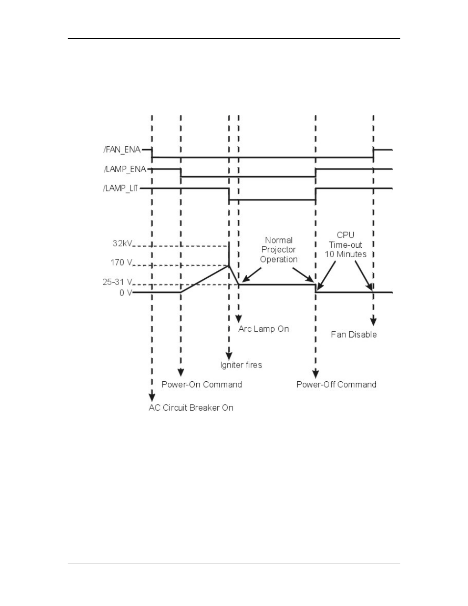
Command ON Timing
Figure 7-10
POWER ON and POWER OFF command timing diagram.
When the AC Circuit Breaker is powered ON, the Low Voltage Power Supply
generates a +5.1 V Standby voltage that goes to the System Controller PCB to
power the CPU and IR Detectors. The Low Voltage Power Supply also puts out
the +24 V Standby voltage (/FAN_ENA goes low) that provides power to the
cooling fans. The cooling fans run from the time the AC Circuit Breaker is
powered ON until approximately ten minutes after the projector receives a power
Off command (AC Circuit Breaker still on).
When the projector receives a power ON command from the IR Remote, PC or
Laptop, the System Controller PCB receives a /LAMP_OK from the Arc Lamp
Power Supply. The System Controller PCB then drives the /LAMP_ENA signal
- 1108TTH-AO-AO (120 pages)
- HD-Z70RX5 (34 pages)
- HD-P61R2U (96 pages)
- HD-65S998 (88 pages)
- DLA-G10U (15 pages)
- DLA-M5000SCU (68 pages)
- LCT2441-001B (162 pages)
- D-ILA DLA-RS40 (78 pages)
- LX-D1010 (4 pages)
- PC007182999-1 (185 pages)
- HD-70FH97 (96 pages)
- DLA-HX2U (62 pages)
- LCT2370-003A (64 pages)
- 335 (16 pages)
- DLA-HD1 (55 pages)
- DLA-HD1 (108 pages)
- DLA-HD1 (2 pages)
- PC007182399-1 (62 pages)
- DLA-SH4K (48 pages)
- D-ILA DLA-HD350 (57 pages)
- HD-61G657 (88 pages)
- 370 SC (163 pages)
- I'Art Pro AV-56P786 (80 pages)
- 1004KGI-II-IM (72 pages)
- LX-P1010ZU (79 pages)
- AV 56WP94 (88 pages)
- HD-55G456 (88 pages)
- HD-61FN97 (96 pages)
- I'Art 1004TNH-II-IM (72 pages)
- AV 48P777 (72 pages)
- CB100 (128 pages)
- HD-56FB97 (88 pages)
- AV 56WP74 (64 pages)
- BHL5006-S (4 pages)
- DLA-HD350 (58 pages)
- DLA-HD350 (173 pages)
- HD-61Z576 (80 pages)
- AV-56WP30 (68 pages)
- DLA-HX2E (62 pages)
- HD-ILA LCT2067-002A-A (96 pages)
- AVO48WP30 (68 pages)
- DLA-SX21U (58 pages)
- I'Art 1003-TN-II-IM (88 pages)
- AV-P960E (109 pages)