Assembly – Jackson 700 Series User Manual
Page 10
ASSEMBLY:
Please ensure the proper tools are used for ease of installation.
Some assemb
e required if this unit is installed in a pedestal.
Please remove
onents from the packaging and inspect all components to ensure there is no damage
to any components in the packa
damage is present please contact you local dealer for replacement
co
nts. P
ace all
ed components with original manufacturer’s parts only no substitutions
will be permitted. Please remove all packaging from all components of the gas grill before operating.
TOLLS REQUIRED FOR ASSEMBLY
ly will b
all comp
ging. If
mpone
lease repl
damag
:
# 2 Ph
rewdriver
8 mm Open Ended Wren
2- 3/4” O
Ended Wren
s
Adjus
ench
SIDE SHELF INSTALLATION.
illips Sc
ch
che
pen
table
Wr
Rem
curing
the front of the Display Panel and the pedestal side ( X 2). Do not
throw
se faste
Remove the
ws from each side of the pedestal.
Loos
mm b
top of each pedestal side. (Do Not Remove)
¾ Carefully remove the Side Shelves from the packaging.
¾ The Side Shelf that contains the Side Burner will ALWAYS be installed on the Left hand side of the
Grill as you are facing the grill.
ead screws to secure the Side Shelf in place.
shelf installation.
¾
ove the se
straps from
away the
4 Phillips he
ners.
ad scre
¾
¾
en the 2- 8
olts at the
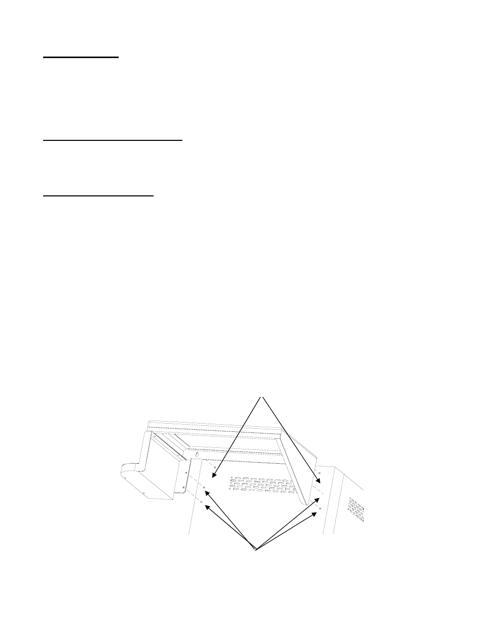
¾ Install the side shelves buy dropping the Side Shelf over the 8 mm bolts. (do not tighten these 8 mm
bolts).
¾ Install the 4 Phillips h
¾ Tighten the 2 – 8 mm bolts to finish the side
¾ Repeat for the other side.
Connect the gas line from the inside of the pedestal to the Side Burner outlet located under the Left Side
helf. Use 2 - 3/4” wrenches to properly secure the gas line to the Side Burner Gas Valve assembly.
S
NOTE: The Condiment bin is already attached to the side shelf as an assembly.
2 – 8mm bolts. Loosen but Do Not remove
4 – Phillips head Screws. Remove and reinstall after side shelf
has been installed on the 2 8 mm bolts at the top
10