Long time integration, Cv-m91 – JAI CV-M91 User Manual
Page 17
CV-M91
- 16 -
6.2.5. Long time integration
The exposure time is the interval between 2 ext. VD pulses sent to the VD input. (Pin No. 7 of
the 12-pin connector). The exposure starts after input of the first ext. VD pulse, and ends after
the next input of the next ext. VD pulse, which again starts a new exposure. The long time
exposure is a continuous process where each external VD will synchronize the camera, stop the
exposure, start a new exposure and read out the previous accumulated signal. The exposure
time can be selected in intervals of complete vertical timing periods. (Interlaced frame: EIA
525H and CCIR 625H. Non-interlaced field EIA 262H and CCIR 312H).
Refer to “7. Configuring the Camera.”
To use this mode:
Set function:
Trigger mode to “Long Time integrationl”. SW 1-4 to OFF
On PK8407: JP301 open, JP302 short, JP311 short.
Accumulation to “Field” or “Frame”. SW 301-4 to OFF or ON
Scanning to “Non-interlaced” or “Interlaced”. SW 1-5 to ON or OFF
Shutter Speed to “OFF ”. SW 1-1 through 1-3 to OFF
Other
functions
Input:
Ext. VD to pin 7 on 12-pin connector
(Ext. HD to pin 7 on 12-pin connector). Option
Important notes on using this mode.
• The exposure range is from 1 field to ∞. However it is recommended not to use exposure
over 2 seconds due visible dark current signals.
• The ext. VD signal should follow the camera sync system and interlace setting.
• Requirements to HD/VD phase is shown in fig. 10.
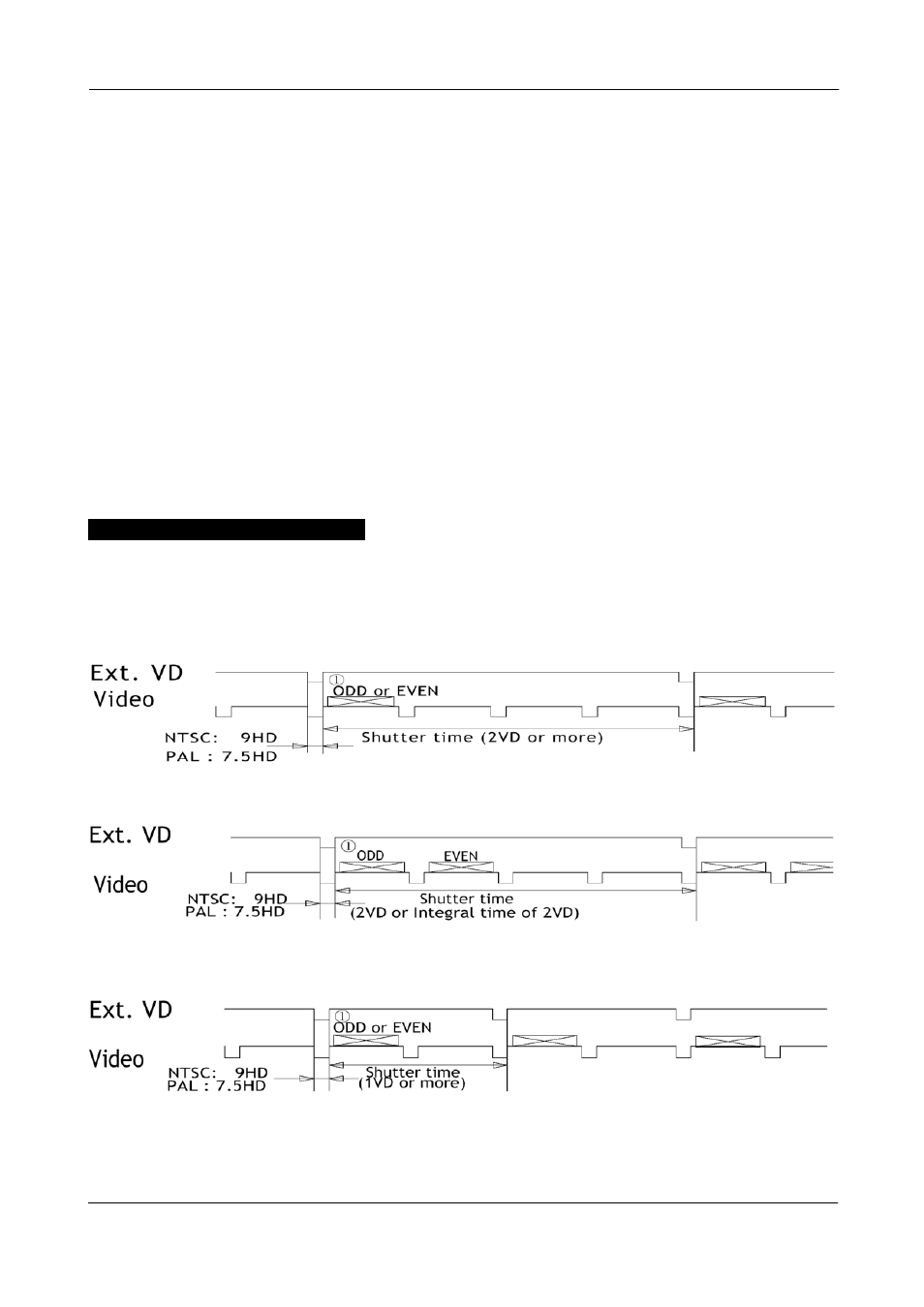
Fig. 27. Long time interlaced field integration
Fig. 28. Long time interlaced frame integration
Fig. 29. Long time non-interlaced field integration