Adjustments, 90 degree positive stop, Scale calibration – Jet Tools 708315BTA User Manual
Page 18: 45 degree positive stop
18
Adjustments
When working around the saw
blade, always disconnect the saw from the
power source! Failure to comply may cause
serious injury!
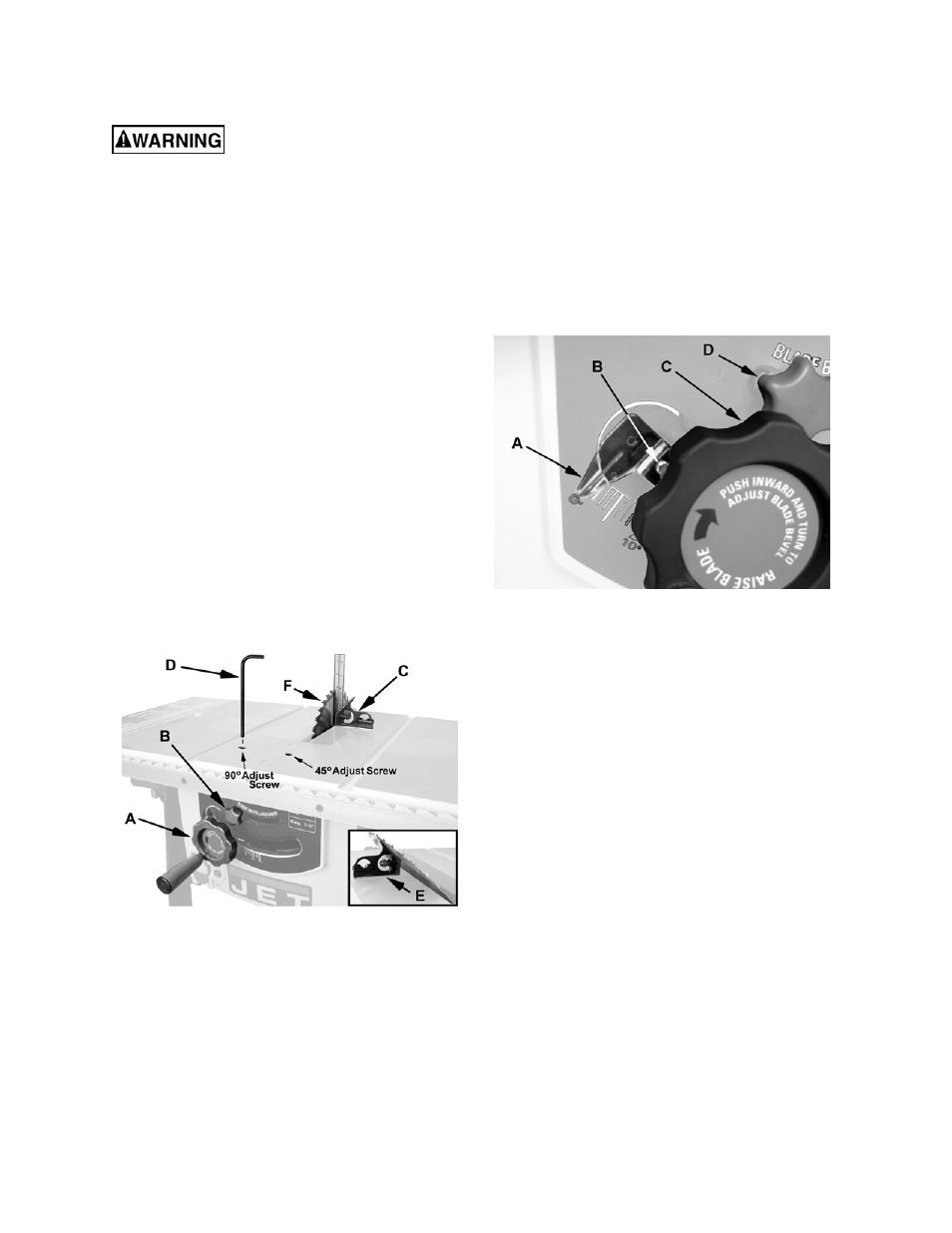
90 Degree Positive Stop
Referring to Figure 19:
1. Turn the handwheel (A) clockwise and raise
the blade to its maximum height.
2. Loosen the blade tilt lock knob (B) by turning
counterclockwise.
3. Push
the
handwheel (A) in to engage the blade
tilt mechanism; then turn clockwise all the way,
bringing the blade to the 90º position to the
table.
4. Continue holding the handwheel with the blade
in this position. Place a combination square (C)
on the table and against the blade as shown.
If the blade is not 90º to the table:
5. While maintaining the hold on the handwheel,
use a 6mm hex wrench to turn the 90 Adjust
Screw (Figure 19) until the blade is 90º to the
table.
6. Tighten
the
blade tilt lock knob (B).
Figure 19
Scale Calibration
The scale next to the handwheel needs to be
calibrated after the saw blade has been calibrated
at the 90º positive stop (see previous section) and
the scale does not indicate 0º.
To calibrate the scale (refer to Figure 20):
1. Loosen the blade tilt lock knob (D) by turning
counterclockwise.
2. Push
the
handwheel (C) in to engage the blade
tilt mechanism; then turn clockwise all the way,
bringing the blade to the 90º position to the
table. Hold the handwheel and:
3. Lock
the
blade tilt lock knob (D).
If the scale does not read exactly 0º:
4. Loosen the screw (B) with an off-set cross-
point screwdriver.
5. Manually adjust the scale (A) until it points
to 0º:
6. Tighten
the
screw (B).
Figure 20
45 Degree Positive Stop
Referring to Figure 19:
1. Turn the handwheel (A) clockwise and raise
the blade to its maximum height.
2. Loosen the blade tilt lock knob (B) by turning
counterclockwise.
3. Push
the
handwheel (A) in to engage the blade
tilt mechanism and turn counterclockwise all
the way, bringing the blade to the 45º position
to the table.
4. Continue holding the handwheel with the blade
in this position. Place a combination square (E)
on the table and against the blade as shown.
If the blade is not 45º to the table:
5. While maintaining the hold on the handwheel,
use a 6mm hex wrench to turn the 45 Adjust
Screw (Figure 19) until the blade is 45º to the
table.
6. Tighten
the
blade tilt lock knob (B).