Assembly, Where to begin, Leg assembly – Jet Tools 708315BTA User Manual
Page 10
10
Assembly
Do not plug the table saw into
the power source until all assembly has been
completed! Failure to comply may cause
serious injury!
Where to Begin
Each assembly section will start by listing the
applicable model(s) for that assembly procedure.
The starting point for your particular model,
however, is as follows:
Models LSA, LSB: start with Leg Assembly below.
Models BTA, BTB, BTC: start with Installing the
Blade Guard and Splitter on page 12.
Leg Assembly
Models LSA, LSB
Follow these Leg Assembly instructions if you plan
to use your saw as a floor model. If this saw is to
be used for bench top applications, skip this section
and proceed to the Extension Table section.
Tools required – 10mm socket and wrench
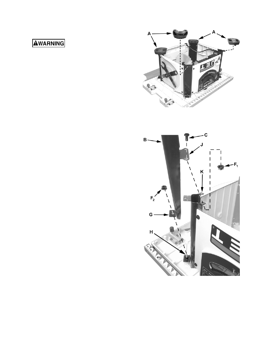
Referring to Figures 1 and 2:
Required hardware (for each leg): two M6x12 hex
cap screws (C) and three M6 flange hex nuts (F).
1. With the saw upside down on the floor, remove
the four rubber feet (A) from each corner of the
base.
2. Take
one
leg (B) and position it so the outside
tab (G), containing the mounting hole, is
towards the bottom.
3. Mount one leg to a corner of the saw base so
the hole in the outside tab (G) lines up with the
screw (H) and the two holes on the leg's inside
tab (J) rests on top of the base tabs (K) with
the mounting holes lined up.
Note: The leg with the WARNING label must be
mounted on the corner of the saw base that also
has the WARNING label.
4. Insert two hex cap screws (C) through the
mounting holes of the leg tab (J) and base tab
(K). Secure with flange hex nuts (F
1
). Hand-
tighten only.
Figure 1
Figure 2
5. Secure the leg's outside tab (G) to the screw
(H) on the base with a flange
hex nut (F
2
).
Hand-tighten only.
Mount two more legs in the same manner
described in steps 1–5. Don't mount the last leg
until the shelf is installed as described in the next
section.