Intel IB850 User Manual
Page 25
INSTALLATIONS
IB850 User’s Manual
21
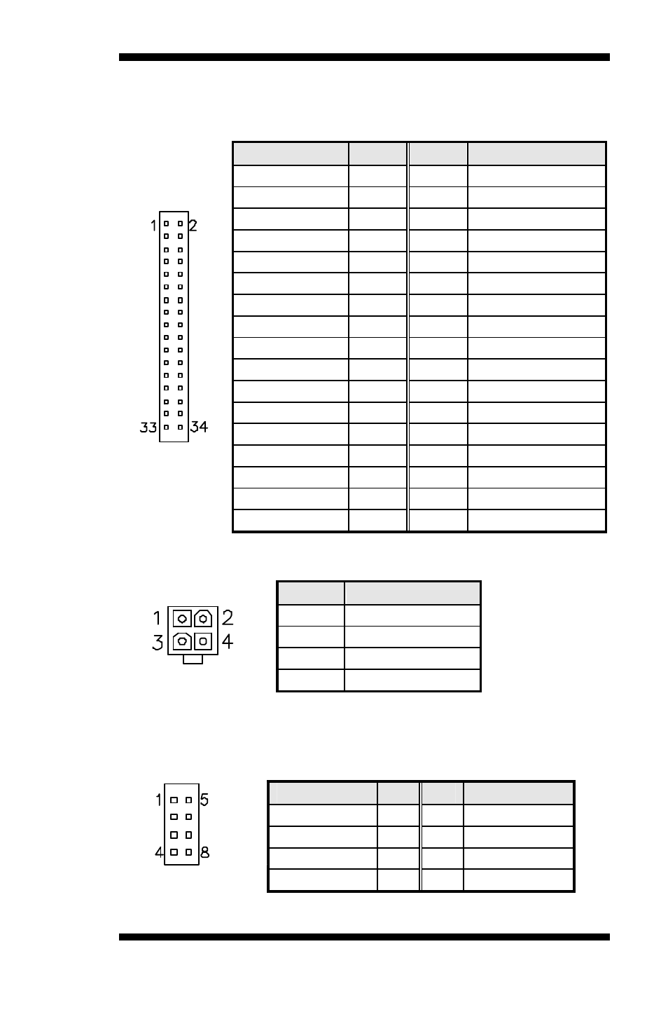
FDD1: Floppy Drive Connector
FDD1 is a 34-pin header and will support up to 2.88MB floppy drives.
Signal Name
Pin #
Pin #
Signal Name
Ground
1
2
RM/LC
Ground
3
4
No connect
Ground
5
6
No connect
Ground
7
8
Index
Ground
9
10
Motor enable 0
Ground
11
12
Drive select 1
Ground
13
14
Drive select 0
Ground
15
16
Motor enable 1
Ground
17
18
Direction
Ground
19
20
Step
Ground
21
22
Write data
Ground
23
24
Write gate
Ground
25
26
Track 00
Ground
27
28
Write protect
Ground
29
30
Read data
Ground
31
32
Side 1 select
FDD1
Ground
33
34
Diskette change
CN1: ATX 12V/+12V Power Connector
Pin #
Signal Name
1
Ground
2
Ground
3
+12V
4
+12V
CN2, CN3: USB Connectors
The following table shows the pin outs of the USB pin headers
connectors. Overall, the two pin headers support four USB ports.
Signal Name
Pin
Pin
Signal Name
Vcc
1
5
Ground
USB0-
2
6
USB1+
USB0+
3
7
USB1-
CN2
Ground
4
8
Vcc
- 41210 (64 pages)
- 8xC251TQ (20 pages)
- ENTERPRISE PRINTING SYSTEM (EPS) 4127 (84 pages)
- U3-1L (20 pages)
- 80960HA (104 pages)
- X58 (54 pages)
- ESM-2850 2047285001R (91 pages)
- ATOM US15W (54 pages)
- D915GVWB (4 pages)
- XP-P5CM-GL (28 pages)
- AX965Q (81 pages)
- CORETM 2 DUO MOBILE 320028-001 (42 pages)
- CV700A (63 pages)
- 80C188EA (50 pages)
- X25-M (28 pages)
- XP-P5IM800GV (26 pages)
- IB868 (60 pages)
- D865GVHZ (88 pages)
- IB865 (64 pages)
- Altera P0424-ND (1 page)
- 8086-2 (30 pages)
- IXDP465 (22 pages)
- IWILL P4D (104 pages)
- GA-8I955X PRO (88 pages)
- FSB400 (PC2100) (96 pages)
- D845GLAD (4 pages)
- NAR-3041 (1 page)
- 87C196CA (136 pages)
- G52-M6734XD (74 pages)
- A96134-002 (10 pages)
- Express Routers 9000 (8 pages)
- 82540EP (45 pages)
- D865GLC (94 pages)
- MB898RF (62 pages)
- Arima LH500 (78 pages)
- V09 (33 pages)
- I/O Processor (22 pages)
- M600 (110 pages)
- SE7520JR2 (63 pages)
- SERVER BOARD S5520HCT (30 pages)
- Extensible Firmware Interface (1084 pages)
- GA-8IPXDR-E (70 pages)
- D845EBG2 (4 pages)
- AW8D (80 pages)