2 headers, Usb port headers – Intel G41 EXPRESS CHIPSET PMG41-D2 User Manual
Page 13
11
3-2 Headers
(1) Line-Out/MIC Header for Front Panel (9-pin): AUDIO
This header is connected to Front Panel Line-out, MIC connector with cable.
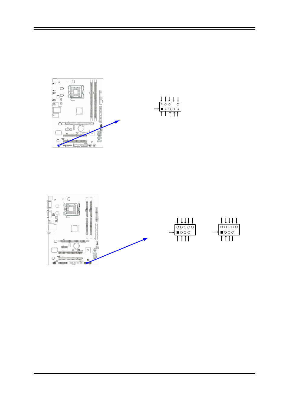
(2) USB Port Headers (9-pin) : USB2 / USB3
These headers are used for connecting the additional USB port plug. By attaching an
option USB cable, your can be provided with two additional USB plugs affixed to the
back panel.
(3) Speaker connector: SPEAK
This 4-pin connector connects to the case-mounted speaker. See the figure below.
(4) Power LED: PWR LED
The Power LED is light on while the system power is on. Connect the Power LED
from the system case to this pin.
(5) IDE Activity LED: HD LED
This connector connects to the hard disk activity indicator light on the case.
(6) Reset switch lead: RESET
This 2-pin connector connects to the case-mounted reset switch for rebooting your
computer without having to turn off your power switch. This is a preferred method of
rebooting in order to prolong the lift of the system’s power supply. See the figure
below.
USB Port Headers
Pin 1
USB2
VC
C
-
DAT
A
GND
+DATA
VC
C
OC
-
DAT
A
GND
+DATA
Pin 1
USB3
VC
C
-
DA
TA
GN
D
+D
AT
A
VC
C
OC
-
DAT
A
GN
D
+DAT
A
Line-Out, MIC Headers
AUDIO
Pin 1
AUD-Lineout2-L
A
U
D
-
MI
C
-
R
AUD-Lineout2-R
SENSE-SEND
GND
SENSE2-RETUR
PRESENCE
2
9
10
KEY
AUD-MIC-L
SENSE1-RETURN