Intel SDS2 User Manual
Page 97
Intel® Server Board SDS2
Connections
Revision 1.2
Order Number: A85874-002
83
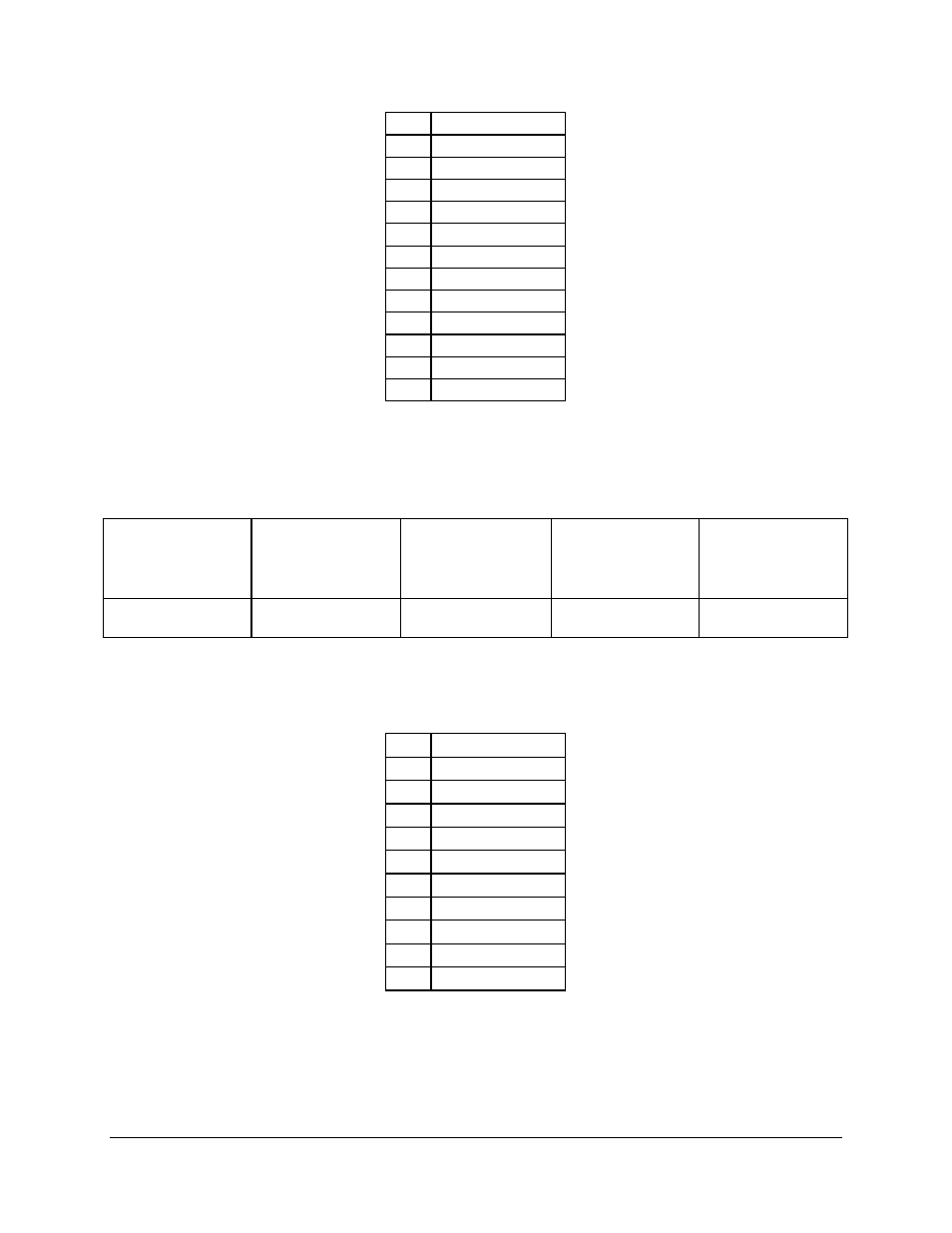
Pin
Signal Name
1
Fused 5 V
2
USB_PORT1_D-
3
USB_PORT1_D+
4
GND
5
Fused 5 V
6
USB_PORT2_D-
7
USB_PORT2_D+
8
GND
9
Fused 5 V
10
USB_PORT3_D-
11
USB_PORT3_D+
12
GND
A 10-pin header (2X5) located at CN18 on the Server Board provides an option to cable out the
USB to the front panel. The pin-out of the header is detailed in the following table that is
representative of the Foxconn HL07051-P9 Housing located at CN18.
Pin 6 +5Volts
Pin 7
USB_PORT4_D-
Pin 8
USB_PORT4_D
+
Pin 9 GND
Pin 10 N/C
Pin 1 N/C
Pin 2 N/C
Pin 3 N/C
Pin 4 N/C
Pin 5 KEY
Table 68. 10-pin USB Connection Header (2 x 5) Pin-out
Pin
Signal name
1
N/C
2
N/C
3
N/C
4
N/C
5
KEY
6
Fused 5 V
7
USB_PORT4_D-
8
USB_PORT4_D+
9
GND
10
N/C
8.6.6
Floppy Connector
The following table details the pin-out of the 34-pin floppy connector.