Intel SDS2 User Manual
Page 26
I/O Subsystem
Intel® Server Board SDS2
Revision 1.2
Order Number: A85874-002
12
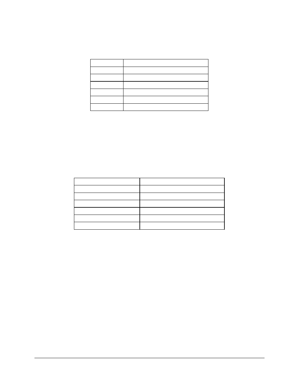
Table 5. P32-A Configuration IDs
IDSEL Value
Device
18
ATI RAGE XL Video Controller
19
Intel
82550 Fast Ethernet Controller 1
20
Intel 82550 Fast Ethernet Controller 2
24
PCI Slot 3
25
PCI Slot 4
31
CSB5 South Bridge
4.1.1.2
P32-A Arbitration
P32-A supports seven PCI masters (ATA RAGE XL, two Intel 82550s, PCI masters from slots 3
and 4, CSB5, and HE-SL).
All PCI masters must arbitrate for PCI access, using resources
supplied by the HE-SL.
The following table defines the arbitration connections.
Table 6. P32-A Arbitration Connections
Baseboard Signals
Device
REQ_VGA / GNT_VGA
ATI* RAGE XL Video Controller
D_PCIREQL1 / D_PCIGNTL1
Intel
82550 Fast Ethernet Controller 1
D_PCIREQL2 / D_PCIGNTL2
Intel
82550 Fast Ethernet Controller 2
D_PCIREQL3 / D_PCIGNTL3
PCI Slot 3
D_PCIREQL4 / D_PCIGNTL4
PCI Slot 4
D_PCIREQL5 / D_PCIGNTL5
CSB5 South Bridge
4.1.2
64-bit, 66-MHz PCI Subsystem
There are two 64-bit, 66-MHz PCI busses directed through the CIOB20 I/O Bridge. Both segments
support full-length, full-height PCI cards. The PCI cards must meet the PCI specification for height,
inclusive of cable connections and memory. The two PCI segments are peer buses.
4.1.2.1
Device IDs (IDSEL)
Each device under the PCI hub bridge has its IDSEL signal connected to one bit of AD [31:16],
which acts as a chip select on the PCI bus segment in configuration cycles. This determines a
unique PCI device ID value for use in configuration cycles. The following tables show the bit to
which each IDSEL signal is attached for P64-B and P64-C devices, and corresponding device
description.