Intel SDS2 User Manual
Page 42
Server Management
Intel® Server Board SDS2
Revision 1.2
Order Number: A85874-002
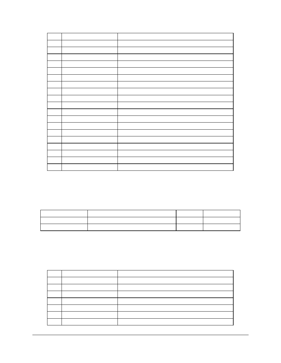
28
Pin
Signal Name
Description
13
N_SM2_CLK
Serial Bus Clock
14
N_SM2_DATA
Serial Bus Data
18
N_ADM_FAN_PWM
Pulse-width modulated output for control of fan speed
19
N_RST_BMCRST_L
Power-on Reset with minimum of 200ms pulse width
29
3VSB
Monitors 3V Standby supply
22
5VSB
Monitors 5V Standby supply
7
3V
Monitors 3V supply
30
5V
Monitors +5V supply
31
-12V
Monitors –12V supply
32
+12v
Monitors +12V supply
33
VCCORE1
Monitors CPU1 core voltage
34
+2.5V
Monitors 2.5V supply
35
VTT
Monitors VTT supply
36
N_SC2VREF3+00
Monitors SCSI channel 2 Terminator 3
37
N_SC2VREF2+00
Monitors SCSI channel 2 Terminator 2
38
N_SC2VREF1+00
Monitors SCSI channel 2 Terminator 1
39
N_SC1VREF3+00
Monitors SCSI channel 1 Terminator 3
40
N_SC1VREF2+00
Monitors SCSI channel 1 Terminator 2
41
N_SC1VREF1+00
Monitors SCSI channel 1 Terminator 1
An 8-bit analog readings of the following system temperatures are provided:
Table 15. Temperature Sensors
Temperature Sensor
Description
Resolution
Accuracy
Primary Processor
Primary processor socket thermal sensor
8-bit
+/- 5°C or better
Secondary Processor
Secondary processor socket thermal sensor 8-bit
+/- 5°C or better
The table below details some of the inputs on Sahalee as used in the SDS2.
Table 16. Sahalee Input Definition
Pin
Signal Name
Description
D12
N_SLOT1OCC_00
CPU1 Presence D etect
D14
N_SLOT2OCC_00
CPU2 Presence Detect
B12
N_FAN1_SENSE_P
CPU1 Fan Speed
A13
N_FAN2_SENSE_P
CPU2 Fan Speed
B13
N_FAN3_SENSE_P
Front System Fan 1 Speed
B14
N_FAN4_SENSE_P
Front System Fan 2 Speed
C13
N_FAN5_SENSE_P
Rear System Fan 1 Speed