8 rear i/o panel, 9 connector manufacturers and part numbers – Intel SDS2 User Manual
Page 101
Intel® Server Board SDS2
Connections
Revision 1.2
Order Number: A85874-002
87
Table 76. External Drive Activity Header Pin-out
Pin
Signal name
1
N/C
2
DRIVE_ACTIVITY
3
DRIVE_ACTIVITY
4
N/C
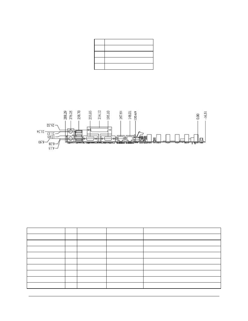
8.8 Rear I/O Panel
The following diagram shows the locations of keyboard, mouse, USB, serial, parallel, video, and
NIC connector interfaces on the system I/O panel, as viewed from the rear of the system.
Figure 10. SDS2 Server Board Rear I/O Panel
8.9 Connector Manufacturers and Part Numbers
The following table shows the quantity and manufacturer’s part numbers for connectors on the
Server Board. Refer to manufacturer’s documentation for more information on connector
mechanical specifications.
Table 77. Server Board Connector Manufacturer Part Numbers
CN Numbers
Qty
Manufacturer
Mfg. Part #
Functional Description
U1, U4
2
Molex*
67276-3708 Rev. 4
P370 processor sockets
DIMM 1-6
6
FOXCONN*
390170-6
168-pin DIMM connectors
11,12,15,16
4
FOXCONN
EH09201-GY-V
64-bit PCI connectors (3.3V)
7, 9
2
FOXCONN
EH06001-GV-V
32-bit PCI connectors (5V)
13, 14
2
FOXCONN
QA11343-P1
68-pin SCSI connectors
30, 31
1
FOXCONN
HL07207-KD2
40-pin IDE connector
24
1
FOXCONN
HL07177-KD4
34-pin floppy connector
3, 4
2
PULSE*
J0026D01B
RJ-45 NIC connectors
27
1
AMP*
11076-4
15-pin DSUB video connector