English, 7) dimm_led, 8) f_panel (2x10 pins connector) – Intel 8S651M-RZ User Manual
Page 16
- 16 -
8S651M-RZ Series Motherboard
English
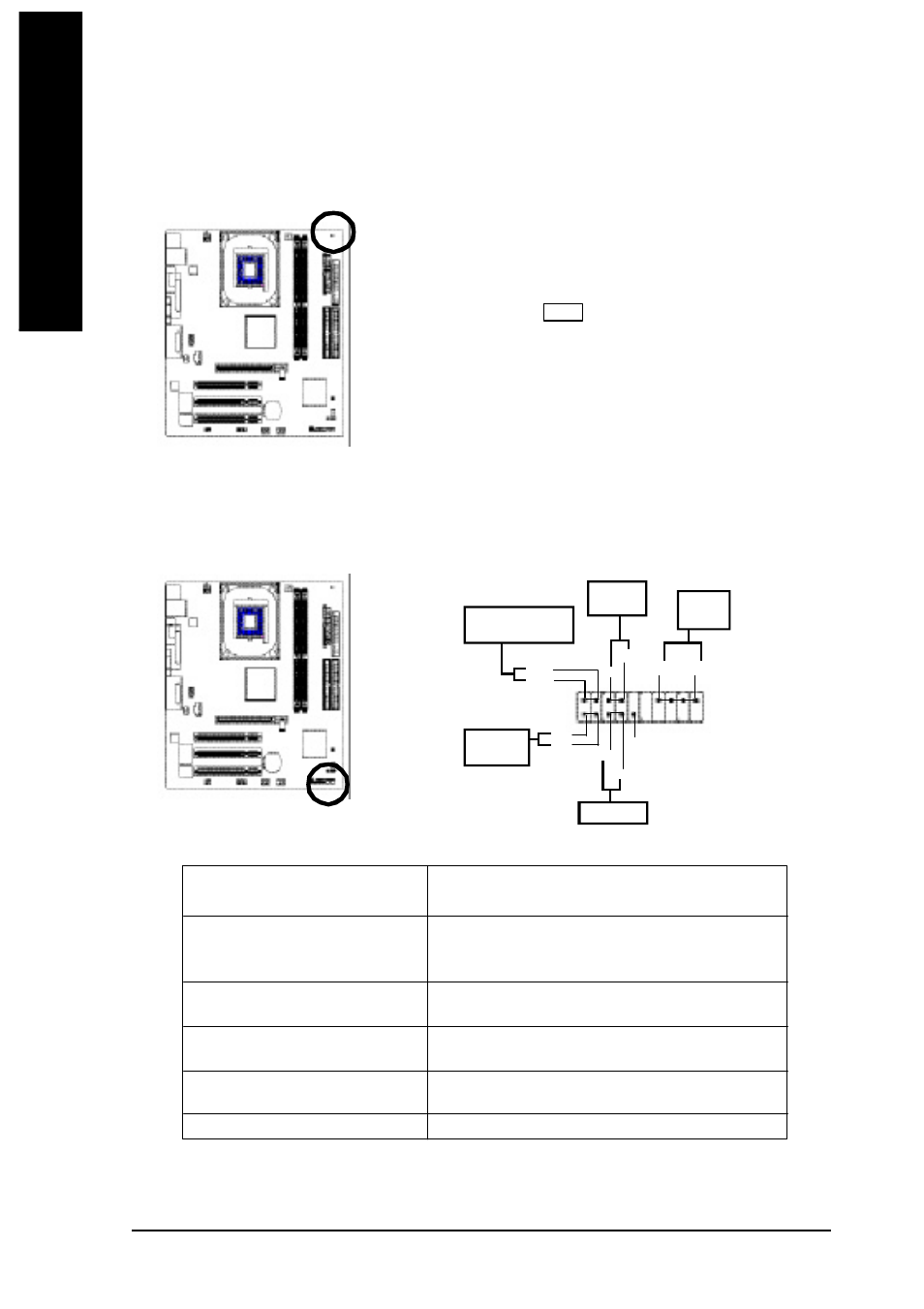
7) DIMM_LED
Do not remove memory modules while DIMM LED is on. It might cause short or other unexpected
damages due to the 2.5V stand by voltage. Remove m emory m odules only when AC Power cord
is disconnected.
+
-
8) F_PANEL (2x10 pins connector)
Please connect the power LED, PC peaker, reset switch and power switch etc of your chassis front
panel to the F_PANEL connector according to the pin assignment above.
HD (IDE Hard Disk Active LED)
Pin 1: LED anode(+)
Pin 2: LED cathode(-)
SPK (Speaker Connector)
Pin 1: VCC(+)
Pin 2- Pin 3: NC
Pin 4: Data(-)
RST (Reset Switch)
Open: Normal Operation
Close: Reset Hardware System
PW (Soft Power Connector)
Open: Normal Operation
Close: Power On/Off
MPD(Message LED/Power/
Pin 1: LED anode(+)
Sleep LED)
Pin 2: LED cathode(-)
NC
NC
SP K-
SPK+
20
Spea ker
Conne ctor
1
19
IDE Hard Di sk
Acti ve L ED
Re set Switch
2
1
So ft Power
Co nnector
1
MPD+
MPD-
Me ssa g e LED/Po we r /
Sle ep L ED
PW -
PW +
1
HD+
HD-
1
RST+
RST-
NC
1