J11: keyboard / mouse connector, J12: power on & reset headers, Sw1: digital i/o input pin switch – Intel MB875 User Manual
Page 21: Led1: digital io output led, Led2: hdd / power led, Cn2, cn3, cn4, cn5: lan connectors, Cn6: usb connector
INSTALLATIONS
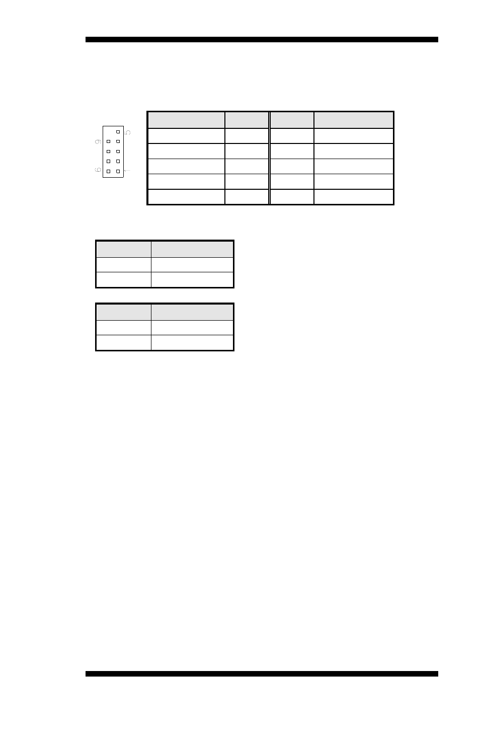
J11: Keyboard / Mouse Connector
J11, a 10-pin header connector, has functions for both keyboard and
mouse. The following table shows the pin assignments of this connector.
Signal Name
Pin #
Pin #
Signal Name
Protect pin
10
5
N.C.
KB clock
9
4
Mouse clock
KB data
8
3
Mouse data
Vcc 7
2 Vcc
Ground 6 1 Ground
J12: Power On & Reset Headers
Pin #
Signal Name
1 PS_ON#
2 Ground
Pin #
Signal Name
3 RESET#
4 Ground
SW1: Digital I/O Input Pin Switch
LED1: Digital IO Output LED
LED2: HDD / Power LED
Red: HDD LED
Green: Power LED
CN2, CN3, CN4, CN5: LAN Connectors
CN2:
LAN1
CN3:
LAN2
CN4:
LAN3
CN5:
LAN4
CN6: USB Connector
MB890 User’s Manual
17
See also other documents in the category Intel Hardware:
- 41210 (64 pages)
- 8xC251TQ (20 pages)
- ENTERPRISE PRINTING SYSTEM (EPS) 4127 (84 pages)
- U3-1L (20 pages)
- 80960HA (104 pages)
- X58 (54 pages)
- ESM-2850 2047285001R (91 pages)
- ATOM US15W (54 pages)
- D915GVWB (4 pages)
- XP-P5CM-GL (28 pages)
- AX965Q (81 pages)
- CORETM 2 DUO MOBILE 320028-001 (42 pages)
- CV700A (63 pages)
- 80C188EA (50 pages)
- X25-M (28 pages)
- XP-P5IM800GV (26 pages)
- IB868 (60 pages)
- D865GVHZ (88 pages)
- IB865 (64 pages)
- Altera P0424-ND (1 page)
- 8086-2 (30 pages)
- IXDP465 (22 pages)
- IWILL P4D (104 pages)
- GA-8I955X PRO (88 pages)
- FSB400 (PC2100) (96 pages)
- D845GLAD (4 pages)
- NAR-3041 (1 page)
- 87C196CA (136 pages)
- G52-M6734XD (74 pages)
- A96134-002 (10 pages)
- Express Routers 9000 (8 pages)
- 82540EP (45 pages)
- D865GLC (94 pages)
- IB850 (69 pages)
- MB898RF (62 pages)
- Arima LH500 (78 pages)
- V09 (33 pages)
- I/O Processor (22 pages)
- M600 (110 pages)
- SE7520JR2 (63 pages)
- SERVER BOARD S5520HCT (30 pages)
- Extensible Firmware Interface (1084 pages)
- GA-8IPXDR-E (70 pages)
- D845EBG2 (4 pages)
- AW8D (80 pages)