Connector locations on mb875 – Intel MB875 User Manual
Page 17
INSTALLATIONS
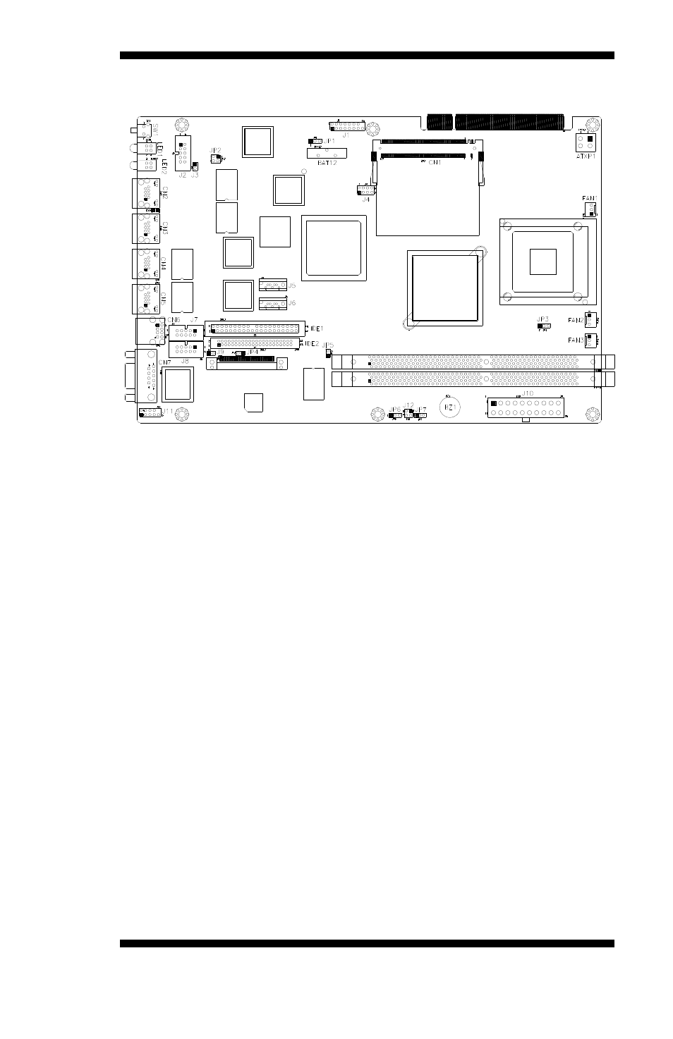
Connector Locations on MB875
Connectors on MB875 ...................................................................... Page
J1: VGA CRT Connector .................................................................... 14
J2: COM2 Serial Port .......................................................................... 14
J4: USB Connector .............................................................................. 14
J5: SATA HDD Connector .................................................................. 15
J6: SATA HDD Connector .................................................................. 15
J7: COM3 Serial Port .......................................................................... 15
J8: COM4 Serial Port .......................................................................... 16
J9: Case Open Detect Header .............................................................. 16
J10: ATX Power Connector ................................................................ 16
J11: Keyboard / Mouse Connector ...................................................... 17
J12: Power On & Reset Headers ......................................................... 17
SW1: Digital I/O Input Pin Switch ...................................................... 17
LED1: Digital IO Output LED ............................................................ 17
LED2: HDD / Power LED .................................................................. 17
CN2, CN3, CN4, CN5: LAN Connectors ........................................... 17
CN6: USB Connector .......................................................................... 17
MB890 User’s Manual
13