10 jumpers and connectors, 4 hardware architectural features, Jumpers and connectors – Intel SROMBSASMR (AXXROMBSASMR) User Manual
Page 18: Hardware architectural features, Figure 9. jumpers and connectors, Table 4. hardware architectural features
Hardware
Intel® Integrated RAID Module SROMBSASMR (AXXROMBSASMR) Technical Product Specification
2.3.10
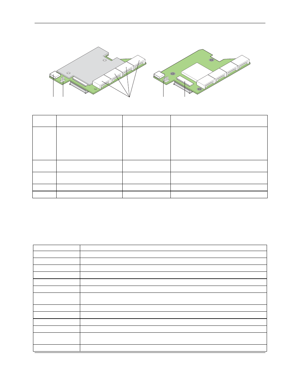
Jumpers and Connectors
AF003065
J1- J4
J6
J7
J5
J8
LSI
Jumper/
Connector
Description
Type
Comments
J1-J4
Internal SAS/SATA Port
Connector, Ports 0-3
N/A
Connection to SAS/SATA devices
J1 = SAS/SATA Port 0
J2 = SAS/SATA Port 1
J3 = SAS/SATA Port 2
J4 = SAS/SATA Port 3
J5
Board-to-board Connector for
Battery Backup Unit
20-pin connector
Provides an interface to the daughter card that
contains the battery backup unit.
J6 Universal
Asynchronous
Receiver/Transmitter (UART)
4-pin connector
Not populated and should not be used.
J7 Keyed
I
2
C Connector
3-pin keyed connector Out-of-band enclosure management (SES2)
J8
Debug Connector
4-pin connector
Reserved
Figure 9. Jumpers and Connectors
2.4 Hardware Architectural Features
Table 4. Hardware Architectural Features
Feature
Intel® Integrated RAID Module SROMBSASMR
RAID levels
0, 1, 5, 6, 10, 50, 60
Number of devices
Up to 16 devices per module
Device types
SAS and SATA hard drives
Data transfer rate
300 MB/s per port
PCI bus
50-pin board-to-board connector with x4 PCI Express*
Memory
128 MB ECC DDR2 667-MHz SDRAM integrated on the module
Battery backup
(optional)
Intel
®
RAID Smart Battery AXXRSBBU3
SAS/SATA connector Four internal SAS/SATA connectors
ROC
LSI* 1078 SAS ROC, which performs hardware exclusive OR (XOR) assistance
Weight 46
oz
Serial port
4-pin serial debug (requires transceiver)
Compatible devices
16 physical devices, 64 logical drives, mixed capacity, SAS and SATA hard drives; non-disk
devices including expanders.
Firmware
4 MB in flash ROM
Revision
1.2
Intel order number E59029-003
12