6 diagnostics, 1 audible alarm, 2 led placement and function – Intel SROMBSASMR (AXXROMBSASMR) User Manual
Page 13: 7 sas / sata connectors, 1 sas / sata connector pin-out, Diagnostics, Sas / sata connectors, Figure 4. sas/sata connectors, Figure 5. sas/sata interface, Table 1. sas/sata connector pin-out
Intel® Integrated RAID Module SROMBSASMR (AXXROMBSASMR) Technical Product Specification
Hardware
2.3.6
Diagnostics
2.3.6.1
Audible Alarm
Audible alarm is not supported.
2.3.6.2
LED Placement and Function
One surface-mounted system error (CRT1) LED (Orange Color) indicates a 1078 ASIC error
resulting from processor-related errors. The LED is off during normal operation and is steady on
during an error condition.
2.3.7
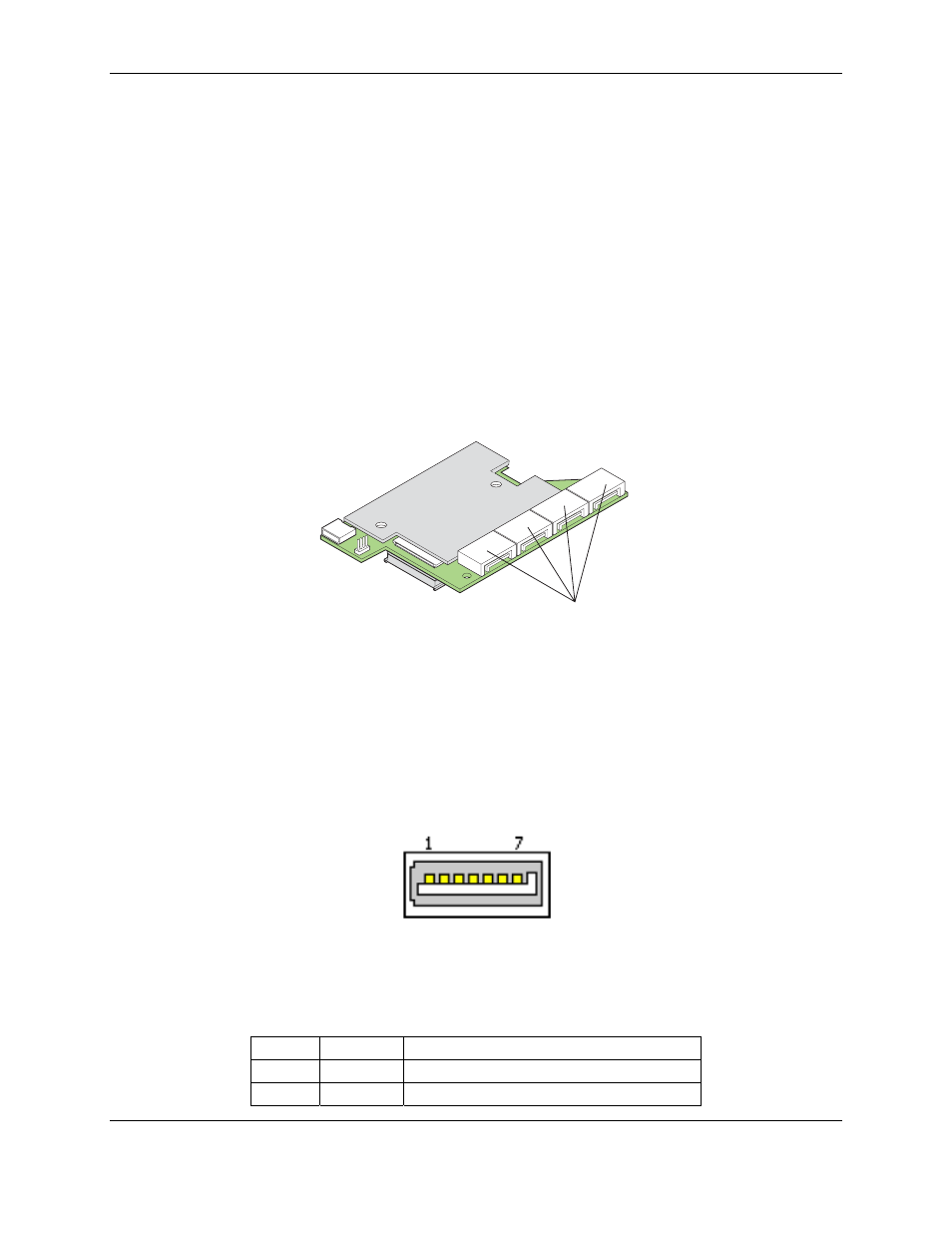
SAS / SATA Connectors
The Intel
®
Integrated RAID Module SROMBSASMR provides four right angle shrouded 7-pin
internal SAS / SATA connectors, each containing one SAS port.
AF003119
SAS/SATA
Connectors
Figure 4. SAS/SATA Connectors
2.3.7.1
SAS / SATA Connector Pin-out
The SAS/SATA connector shown in the following figure is the standard 7-pin SATA internal
connector used by the Intel
®
Integrated RAID Module SROMBSASMR. These pin-outs for the
serial ATA connector are not compatible with the legacy PATA connector.
Figure 5. SAS/SATA Interface
Table 1. SAS/SATA Connector Pin-out
Pin #
Signal
Description
1 GND
Ground
2
TX0+
Transmitter differential pair
Revision 1.2
Intel order number E59029-003
7