Intel Integrated Touchscreen Computer J2 650 User Manual
Page 30
650 System Manual (Draft)
Version 0.4 August 20, 2008
30
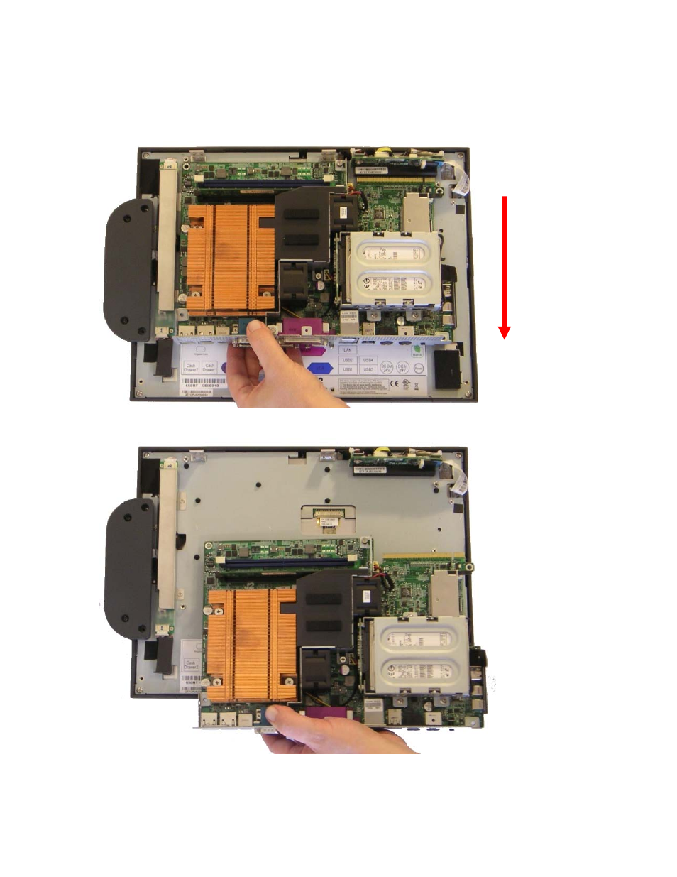
After the screws are removed the system board can be unplugged from its connector.
While using the I/O bracket to pull on, slide the board out towards the bottom of the unit
as shown.
When reinstalling the system board make sure the locking tabs on the bottom of the board
lock into their mating slots.
See also other documents in the category Intel Computers:
- System Board G4H875-N (124 pages)
- LV22N Series (97 pages)
- Pentium 4 Processor Motherboard GA-8I865GME (72 pages)
- NETWORK PROCESSOR IXP2800 (430 pages)
- S5500WB (9 pages)
- System Board G4H875-C (129 pages)
- TIGI2U (26 pages)
- SE8500HW4 (132 pages)
- ISP1100 (81 pages)
- C50277-001 (73 pages)
- ESM-2740 (93 pages)
- SR6850HW4 (119 pages)
- SC5600 (24 pages)
- DP45SG (86 pages)
- SERVER SYSTEM SR2500AL (210 pages)
- GA-N680SLI-DQ6 (112 pages)
- SOCKET 370 CELERON TS-ASP3 (61 pages)
- NetStructure MPCBL0001 (198 pages)
- SROMBSASMR (AXXROMBSASMR) (40 pages)
- Express 5800 TM700 (132 pages)
- SE7520BD2 (64 pages)
- SR9000MK4U (258 pages)
- GS-SR195V (56 pages)
- OCPRF100 MP (149 pages)
- MINI-ITX BOARD AR-B1890 (44 pages)
- SDS2 (145 pages)
- SE7520BD2-D2 (27 pages)
- SC5650 (22 pages)
- Board SE7520BB2 (17 pages)
- CHIPSET 820E (239 pages)
- GS-SR168 (52 pages)
- Express 5800/120Ld (194 pages)
- 7400 (16 pages)
- PCM-3370 (128 pages)
- S5000XAL (113 pages)
- ECB-870 (115 pages)