How to read a command-line syntax diagram – IBM GC23-7753-05 User Manual
Page 12
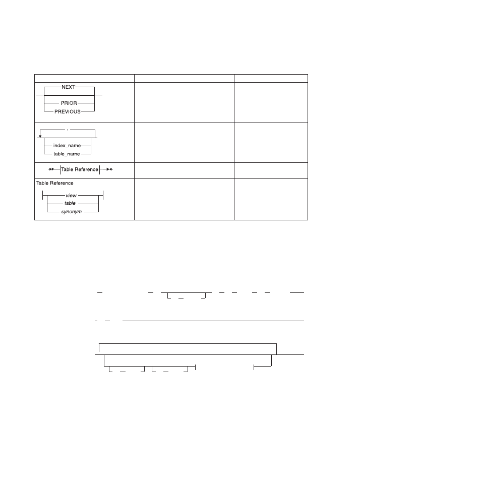
Table 3. Syntax Diagram Components (continued)
Component represented in PDF
Component represented in HTML
Meaning
.---NEXT---------.
----+----------------+---
+---PRIOR--------+
’---PREVIOUS-----’
The values below the main
line are optional, one of
which you might specify. If
you do not specify an item,
the value above the line is
used by default.
.-------,-----------.
V
|
---+-----------------+---
+---index_name---+
’---table_name---’
Optional items. Several items
are allowed; a comma must
precede each repetition.
>>-| Table Reference |-><
Reference to a syntax
segment.
Table Reference
|--+-----view--------+--|
+------table------+
’----synonym------’
Syntax segment.
How to read a command-line syntax diagram
Command-line syntax diagrams use similar elements to those of other syntax
diagrams.
Some of the elements are listed in the table in Syntax Diagrams.
Creating a no-conversion job
onpladm create job
job
-p
project
-n
-d
device
-D
database
-t
table
(1)
Setting the Run Mode
-S
server
-T
target
Notes:
1
See page Z-1
This diagram has a segment named “Setting the Run Mode,” which according to
the diagram footnote is on page Z-1. If this was an actual cross-reference, you
would find this segment on the first page of Appendix Z. Instead, this segment is
shown in the following segment diagram. Notice that the diagram uses segment
start and end components.
x
IBM Informix Installation Guide for Windows