Diagram 5 – Impex EVE-890 User Manual
Page 10
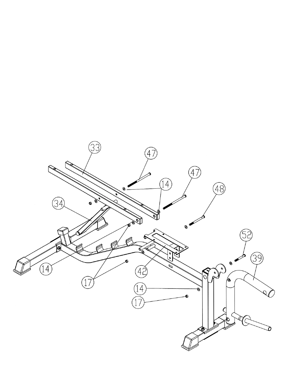
STEP 5 (See Diagram 5)
A.) Attach the side-holes on the Backrest Supports (#33) to the long pivot on the Main
Seat Support (#30). Insert one M10 x 7 ¼” Allen Bolt (#47) through the holes and
secure it with two Ø ¾” Washers (#14), and one M10 Aircraft Nut (#17).
B.) Place the Backrest Incline Support (#34) in between the two Backrest Supports (#33).
Align the holes and secure it with one M10 x 7 ¼” Allen Bolt (#47), two Ø ¾” Washers
(#14), and one M10 Aircraft Nut (#17). Do not tighten the Nuts and Bolts yet. Attach
the other end to a selected slot on the Main Seat Support.
C.) Attach the Seat Incline Support (#42) to the short pivot on the Main Seat Support.
Secure it with a M10 x 4 ¾” Allen Bolt (#48), two Ø ¾” Washers (#14), and one M10
Aircraft Nut (#17).
D.) Attach the Leg Developer (#39) to the open bracket on the Main Seat Support. Secure
it with one M10 x 3 1/8” Allen Bolt (#52), two Ø ¾” Washers (#14) and one M10
Aircraft Nut (#17).
E.) Tighten all Nuts and Bolts previously installed but make sure the Backrest Incline
Support, Backrest Support, Seat Incline Support, and Leg Developer are able to
swivel on the pivots.
DIAGRAM 5
9