Diagram 8 – Impex MWM-1840 User Manual
Page 19
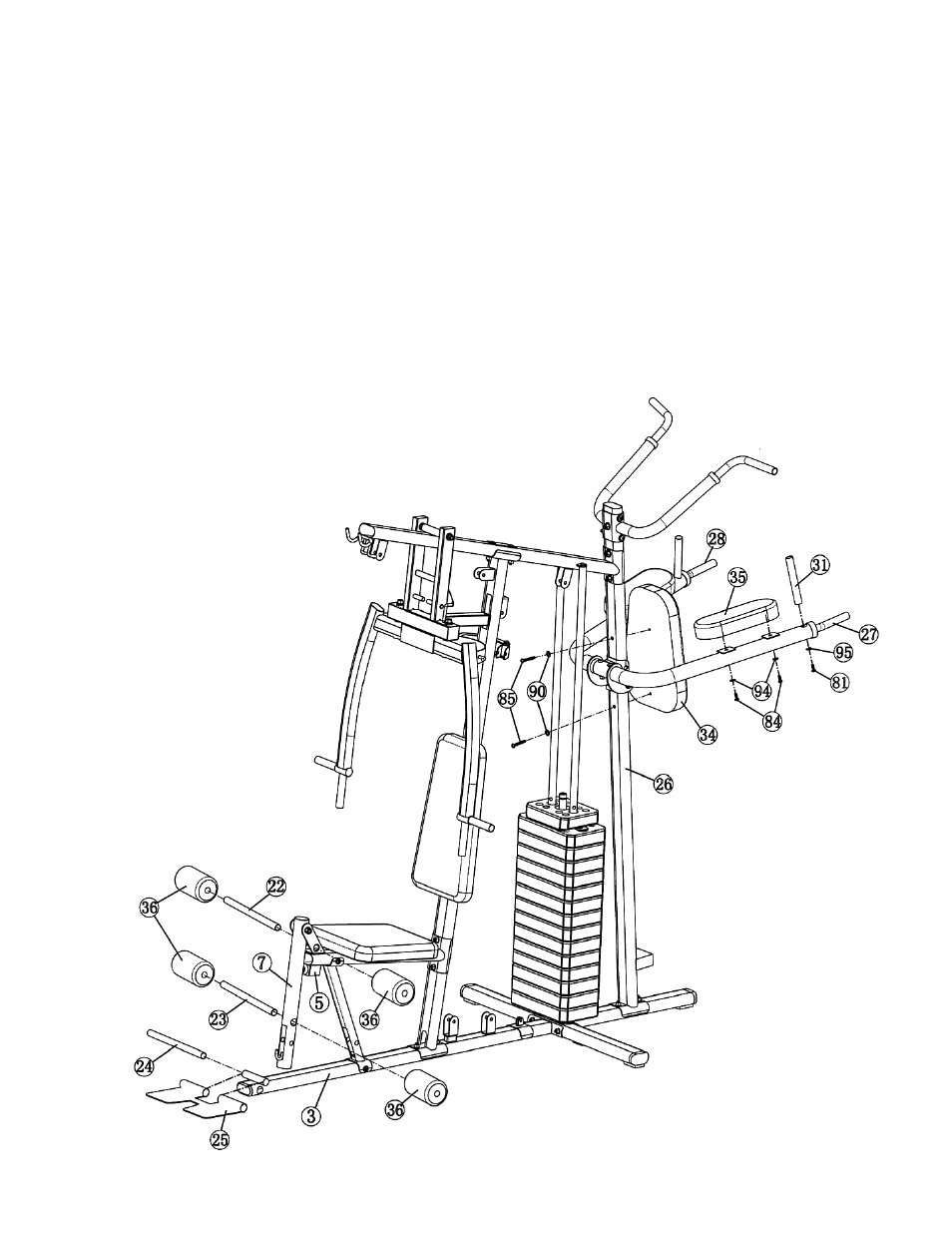
STEP 8 (See Diagram 8)
A.) Attach the Power Station Arm Pads (#35) to the Right & Left Dip Support (#27 & #28).
Secure each Arm Pad with two M8 x 2 ¾” Allen Bolts (#84) and two Ø 5/8” x 1” Curved
Washers (#94).
B.) Attach two Vertical Handles (#13) to Right & Left Dip Support. Secure each Handle to
each Support with one M10 x 1” Allen Bolt (#81) and Ø ¾” x 1 1/8” Curved Washer
(#95).
C.) Insert 15 ¾” Long Foam Tube halfway through the hole on Seat Support (#5). Insert 15”
Short Foam Tube (#23) halfway through the hole on Leg Developer (#7). Push four
Foam Rolls (#36) onto the Tubes from each end.
D.) Attach the Foot Plate (#25) to the pivot on Base Frame (#3). Insert the Foot Plate Axle
(#24) through the Foot Plate and the pivot to secure the Foot Plate to the Base Frame.
DIAGRAM 8
18
- IGS-09 (11 pages)
- SAG-44.1 (10 pages)
- TSA-5682 (14 pages)
- IGS-10 (10 pages)
- TC-6000 (12 pages)
- MWB-715N (12 pages)
- CR 5 (26 pages)
- MD-823 (15 pages)
- PL-43211 (14 pages)
- PL 10510 (12 pages)
- WM-1505 (22 pages)
- PHE1000 (20 pages)
- TSA-5762 (14 pages)
- IGS-5683 (13 pages)
- DBR 400 (7 pages)
- MWM7150 (21 pages)
- DBR 90 (11 pages)
- CG 1400 (24 pages)
- SB 208 (9 pages)
- IGS-02 (10 pages)
- MWB-356 (13 pages)
- AX-PWR7 (21 pages)
- MWB-855 (11 pages)
- TSA-410 (10 pages)
- TSA-41 (7 pages)
- WM 1403 (22 pages)
- DBR 92 (11 pages)
- MARCY TPL-40 (3 pages)
- MSS-1280 (27 pages)
- JD 2 (8 pages)
- PHC-700 (12 pages)
- Gold's Gym WMGG-224 (11 pages)
- MWM 800 (23 pages)
- WM-356 (13 pages)
- EVE-720 (13 pages)
- BF-1201 (22 pages)
- PT 360 (9 pages)
- CB-200 (11 pages)
- Olympic Cage (24 pages)
- EVE-900 (21 pages)
- PT-36 (7 pages)
- PHC-PWR9 (22 pages)
- MWM-1558 (20 pages)
- MWB-4360 (33 pages)