Please read – Motorola POWERBROADBAND T2-2500 User Manual
Page 24
Installation
Steps
Motorola, Inc.
549453-001-00-a
Page 24 of 51
I
I
n
n
s
s
t
t
a
a
l
l
l
l
a
a
t
t
i
i
o
o
n
n
S
S
t
t
e
e
p
p
s
s
PLEASE READ
mT2 features Adaptive Line Power (ALP) for the WallPlates. Follow these instructions when installing the mT2
system. Note that line power is not enabled until after a successful link using an external power supply. Consult the
Appendix for Electrical Safety Information.
PLEASE READ
The following instructions assume knowledge and skills with installing xDSL systems. The details below are relevant
to the mT2 installation. This is not intended to be a step by step training guide. Please consult your Motorola PBN
sales representative if you require training in the installation steps.
I
I
n
n
s
s
t
t
a
a
l
l
l
l
m
m
T
T
2
2
s
s
w
w
i
i
t
t
c
c
h
h
i
i
n
n
p
p
h
h
o
o
n
n
e
e
r
r
o
o
o
o
m
m
;
;
M
M
D
D
F
F
o
o
r
r
I
I
D
D
F
F
1. Install mT2a to equipment rack using the rack-
mount ears provided
2. Connect the AC line cord to the IEC320 male
receptor on the rear of the unit
I
I
n
n
s
s
t
t
a
a
l
l
l
l
c
c
r
r
o
o
s
s
s
s
c
c
o
o
n
n
n
n
e
e
c
c
t
t
s
s
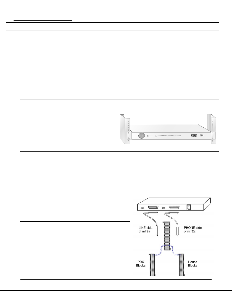
3. Siemens S66M2-5W-TP is the recommended cross connect block. Note the “TP” on the part number.
4. Connect the LINE side mT2 RJ21 to the left side of the S66M2-5W-TP block using a M/M RJ21 telco cable
5. Connect the PHONE side mT2 RJ21 to the right side of the S66M2-5W-TP block using a M/M RJ21 telco
cable
6. Cross-connect line one of each room.
o
Wire pair from the PBX is connected to the left
side of the block
o
Wire pair from the House is connected to the
right
side of the block
R
R
e
e
v
v
i
i
e
e
w
w
t
t
h
h
e
e
c
c
r
r
o
o
s
s
s
s
-
-
c
c
o
o
n
n
n
n
e
e
c
c
t
t
s
s
Before proceeding to the configuration and in-room installation,
review the cross-connects to ensure:
7. No pairs are split, or double-punched
8. Only line 1 of each room is connected
9. Install HV label (supplied) to punch block cover