Installation, 5 communication connections – MGE UPS Systems 250A User Manual
Page 15
34020201EN/AB
- Page 15
Q2
Q1
RS-232
RS-485
1
2
3
2. Installation
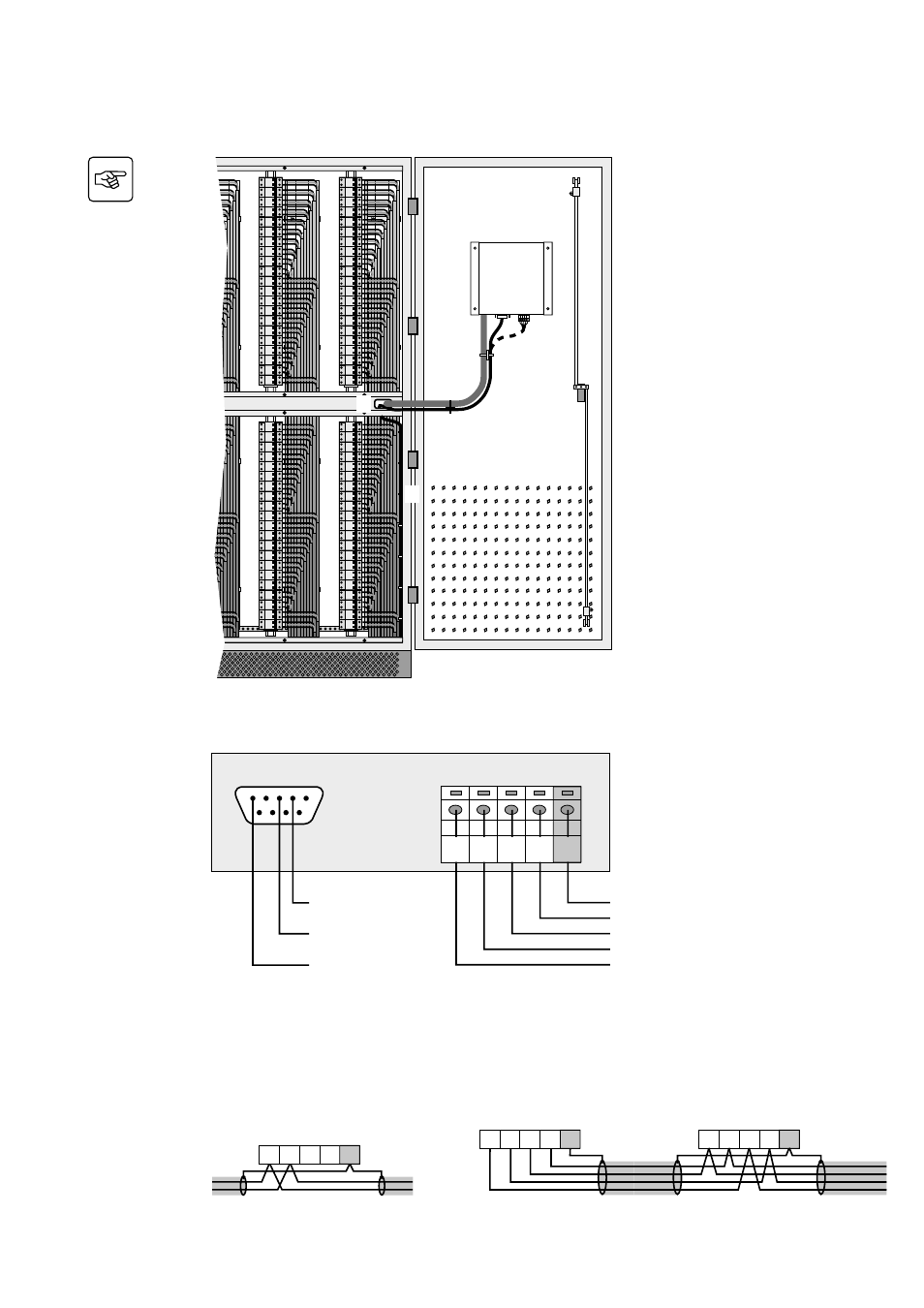
2.5 Communication connections
1. Connect the communication cable to the
RS232 or RS485 connector on the right-
hand door of the module.
2. Run the cable as shown in the figure
opposite.
3. Tie the cable down to the module frame.
Communication connector details
RS485 connector
2 wires
GND
Tx+
Tx-
Tx+ / Rx+
Tx- / Rx-
RS485 connector
4 wires
GND
Rx+
Rx-
Not used
Not used
Td (from the PMM
display)
Rd (to the PMM display)
GND
RS232 connector
RS-485
RS-232
1
2
3
4
5
6
7
8
9
5
4
3
2
1
Example of an RS485 2-wire
connection:
Example of an RS485 4-wire connection:
Master
Slave
Master or slave
5
4
3
2
1
Tx- / Rx-
Tx+ / Rx+
GND
5
4
3
2
1
Rx-
Rx+
GND
Tx-
Tx+
Rx-
Rx+
GND
Tx-
Tx+
5
4
3
2
1
See also other documents in the category MGE UPS Systems Tools:
- Pulsar EX 1000 (28 pages)
- 4.5 kVA (32 pages)
- 1100 (196 pages)
- EPS 8000 (54 pages)
- S EXB 2500 (22 pages)
- Pulsar Extreme 3200C (28 pages)
- ESV 22+Rack (24 pages)
- GES-801L (22 pages)
- Comet EX 7 RT 3:1 (38 pages)
- EX 11RT (72 pages)
- Galaxy PW (44 pages)
- 3 (34 pages)
- Pulsar TM 30 (18 pages)
- 22+ EB 22 (44 pages)
- 1500C (28 pages)
- Rackmount PDU (36 pages)
- Pulsar Esprit 313.5 kVA (6 pages)
- EX-5 (76 pages)
- 30A (30 pages)
- AmpMeter PDU (52 pages)
- EX30 (106 pages)
- 1100 Tower (36 pages)
- 40-75KVA (56 pages)
- 2000 (34 pages)
- 4000 RT (38 pages)
- Pulsar EXtreme C UPS 1500 VA (4 pages)
- FlexPDU 6 AUS (12 pages)
- POWER-SURE 700 (52 pages)
- EX 1000 (28 pages)
- EX7 (18 pages)
- EX30Rack (24 pages)
- 12280 kVA (13 pages)
- 40-150kVA (56 pages)
- 100 (32 pages)
- Uninterruptible Power Provider (4 pages)
- EPS 7000 (62 pages)
- 300 (6 pages)
- EX10Rack (22 pages)
- 500 (4 pages)
- EPS 6000 (84 pages)
- S3 (64 pages)
- EX RT CLA (6 pages)
- 3000 (32 pages)
- 3.5 to 21 kVA N+1 (54 pages)