Chapter 2 tour of product, 1 usb adapter, 1 led indication – MicroNet Technology SP907NL User Manual
Page 7
4
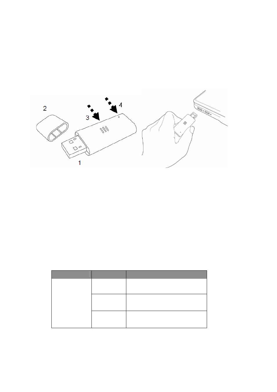
Chapter 2 Tour of Product
2.1 USB
Adapter
1. USB
Connector:
insert this side of the device into an available USB slot.
2. Connector
Cab:
for protecting device when not in use.
3. WPS
button:
located on the bottom side of the device for activating WPS
pairing mode.
4. Link/Activity
LED: indicate device is in use or traffic activity is evident.
2.1.1 LED Indication
LED
Status
Operation
On
Successful connection to AP
or Router
Flashing
Transmitting data to AP or
Router
Link/Activity
Off
No link to AP or Router/
WLAN function is disabled