6. use of indicator lights for troubleshooting – Miller Electric MR-5 User Manual
Page 25
5
-
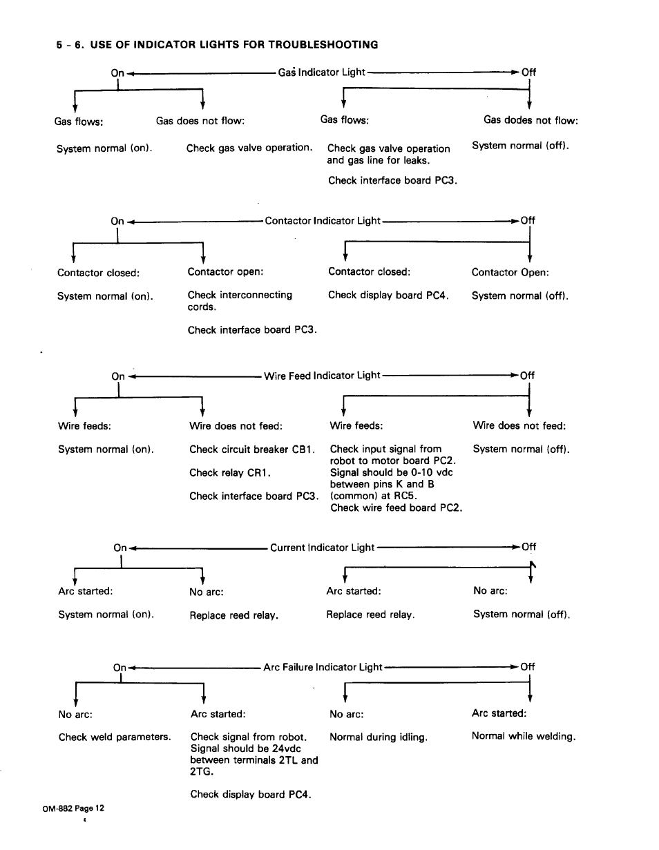
6. USE OF INDICATOR LIGHTS FOR TROUBLESHOOTING
Ga~ Indicator Light
I
Gas does not flow:
IF
Gas flows:
IF
Gas dodes not flow:
System normal (on).
Check gas valve operation.
Check gas valve operation
and gas line for leaks.
Check interface board PC3.
System normal (off).
-Contactor Indicator Light
Contactor closed:
System normal (on).
I,
IF
Contactor open:
Check interconnecting
cords.
Check interface board PC3.
Contactor closed:
Check display board PC4.
IF
Contactor Open:
System normal (off).
Wire Feed Indicator L.~,1
Wire feeds:
System normal (on).
Wire does not feed:
Check circuit breaker CB1.
Check relay CR1.
Check interface board PC3.
Wire feeds:
Check input signal from
robot to motor board PC2.
Signal should be 0-10 vdc
between pins K and B
(common) at RC5.
Check wire feed board PC2.
IF
Wire does not feed:
System normal (off).
On
I
—
Arc started:
System normal (on).
Current Indicator Light
No arc:
Replace reed relay.
Arc started:
Replace reed relay.
•Off
V
No arc:
System normal (off).
Arc Failure Indicator Ligl~
II
No arc:
Arc started:
Check weld parameters.
Check signal from robot.
Signal should be 24vdc
between terminals 2TL and
2TG.
Check display board PC4.
No arc:
Normal during idling.
Arc started:
Normal while welding.
On
Gas flows:
Off
On
Off
On
,~.1
On
-Off
OM-882 Page 12