5. troubleshooting chart – Miller Electric MR-5 User Manual
Page 23
c.
Slide spacers onto new meter support.
d.
Push meter into socket with meter supports
protruding through to rear of PC4.
e.
Reinstall lock washers and nuts to secure
meter to board. Do not
overtighten nuts or
meter may be damaged.
6. To install replacement display board, carefully
line board up with front panel openings for
meters and LED’s.
7.
Reinstall securing screws.
8.
Reconnect PLG2O and PLG24 to matching
receptacles on new PC4.
9.
Reinstall unit top cover.
B. Motor Board PC2 Replacement
1.
Remove unit top cover.
2.
Remove securing screw and unlatch standoff.
3. Gently pull board from receptacle RC5.
4.
Insert new board into RC5.
5.
Reinstall securing screw and latch standoff.
6.
Reinstall unit top cover.
C.
Replacement
Procedure
For
Remaining
Boards
1.
Remove unit top cover and locate board.
2. Disconnect plug(s) from board.
3.
Unlatch standoffs and
ing rail.
slide board
out
of retain-
WARNING:
4.
Slide new board into retaining rail and latch
stan-
doffs.
5. Connect plug(s) to matching receptacle(s) on
new board.
6. Reinstall unit top cover.
5 -5. TROUBLESHOOTING CHART
ELECTRIC SHOCK can kill.
•
Do not touch live electrical parts.
•
Shut down unit, welding powersource, and robot
and disconnect ,nput power employing
‘lockout/tagging procedures” before internally
inspecting or servicing.
Lockout/tagging procedures consist of padlocking line
disconnect switch in open position, removing fuses
from fuse box, or shutting off and red-tagging circuit
breaker or other disconnecting device.
MOVING PARTS can cause serious injury.
•
Keep clear of moving parts.
HOT SURFACES can cause severe burns.
•
Allow cooling period before servicing.
Troubleshooting to be performed only by qualified per-
sons.
It is assumed that the computer interface was properly
installed according to Section 2 of this manual, the
operator is
familiar with the function of controls, the
unit was working properly, and that the trouble is not
related to the
welding process. The following chart is
designed to diagnose and provide remedies for some of
the troubles that may develop in this unit.
Use this chart in conjunction with the circuit diagrams
while performing troubleshooting procedures. If the
trouble is not remedied after performing these pro-
cedures, the nearest Factory Authorized Service Sta-
tion should be contacted. In all cases of equipment
malfunction, the
manufacturer’s recommendations
should be strictly followed.
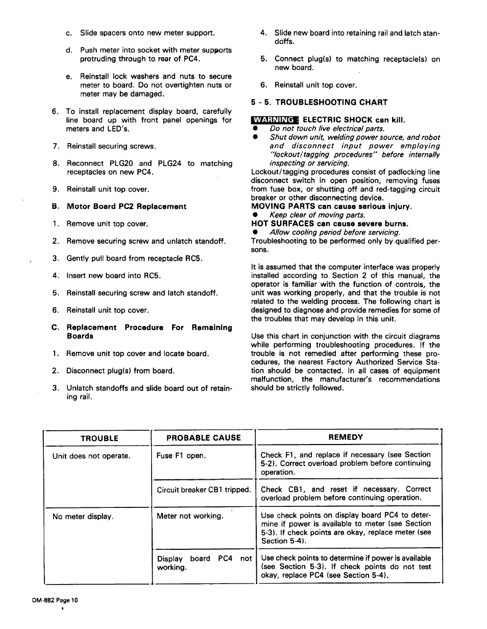
TROUBLE
PROBABLE CAUSE
REMEDY
Unit does not operate.
Fuse Fl open.
Check Fl, and replace if necessary (see Section
5-2). Correct overload problem before continuing
operation.
Circuit breaker CB1 tripped.
Check CBl, and reset if necessary. Correct
overload problem before continuing operation.
No meter display.
Meter not working.
Use check points on display board PC4 to deter
mine if power is available to meter (see Section
5-3). If check points are okay, replace meter (see
Section 5-4).
Display board
PC4 not
working.
Use check points to determine if power is available
(see Section 5-3). If check points do not test
okay, replace PC4 (see Section 5-4).
OM-882 Page 10