1. general information and safety, 2. receiving-handling, 3. description – Miller Electric MR-5 User Manual
Page 15: 2 - installation, 1. location, Installation
1
-
1. GENERAL INFORMATION AND SAFETY
A.
General
Information presented in this manual and on various
labels, tags, and plates on the unit pertains to equip-
ment design, installation, operation, maintenance, and
troubleshooting which should be read, understood, and
followed for the safe and effective use of this equip-
ment.
B. Safety
The installation,
operation,
maintenance, and
troubleshooting of arc welding equipment requires
practices and procedures which ensure personal safety
and the safety of others. Therefore, this equipment is to
be installed, operated, and maintained only by qualified
persons in accordance with this manual and all ap-
plicable codes such as, but not limited to, those listed at
the end of Section 1
-
Safety Rules For Operation Of
Arc Welding Power Source in the welding power source
Owner’s Manual.
Safety instructions specifically pertaining to this unit ap-
pear throughout this manual highlighted by the signal
words
and
which identify
different levels of hazard.
WARNING
CAUTION
carefully followed could result in minor personal injury
or damage to this equipment.
A third signal word,
•s•s,
highlights instruc-
tions which
need special emphasis to obtain the most
efficient operation of this equipment.
1
-
2. RECEIVING-HANDLING
-
Before installing
this equipment, clean all packing material from around
the unit and carefully inspect for any damage that may
have occurred during shipment. Any claim for loss or
damage that may have occurred in transit must be filed
by the purchaser with the carrier. A copy of the bill
of lading will be furnished by the manufacturer on re-
quest if occasion to file claim arises.
When requesting information concerning this equip-
ment, it is essential that Model Description and Serial
Number of the equipment be supplied.
1
-
3. DESCRIPTION
-
The computer interface con-
trol contains wire feed speed, weld voltage, and weld
amperage control circuitry, digital ammeter, voltmeter,
and wire feed speed meter, and circuitry to interface
with the robot control. The control is shipped for opera-
tion in the constant voltage mode but has constant cur-
rent capabilities.
WARNING
CAUTION
statements include installation, operation,
and maintenance procedures or practices which if not
carefully followed could result in serious personal injury
or loss of life.
statements include installation, operation,
and maintenance procedures or practices which if not
SECTION 2
-
The gas/current sensing control contains the gas valve
and current sensing reed relay.
These components function with the robot system
when using the Gas Metal Arc Welding (GMAW) pro-
cess.
INSTALLATION
2
-
1. LOCATION (Figure 1-1)
The location should allow room to open and remove
covers and wrappers for installation, maintenance, and
repair. Lead lengths must be considered when locating
components.
Mounting holes are provided in each component for
mounting purposes. Figure 1-1 gives unit dimensions.
Normally the computer interface is mounted on top of
the robot control unit. The gas/current sensing control
should be mounted in line between the welding power
source and wire drive assembly. See installation section
of robot manual for specific information.
The service life and efficiency of the system are reduced
when it is subjected to high levels of dust, dirt,
moisture, corrosive vapors, and extreme heat.
re-114 347
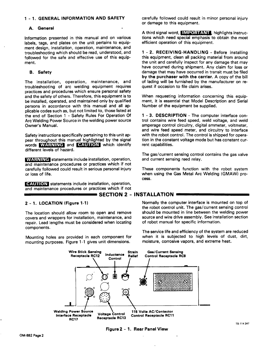
Wire Stick Sensing
Strain
Gas/current Sensing
Receptacle RC12
Inductance
Relief
control Receptacle RC9
control
Welding Power Source
115 Volts Ac/contactor
Interface Receptacle
Voltage control
control Receptacle Rd 1
RC17
Receptacle RC13
Figure 2
-
1. Rear Panel View
OM-882 Page 2