Miller Electric MR-5 User Manual
Page 17
A. Wire Stick Sensing Connections
1.
Align keyway, insert
four-socket Amphenol plug
into matching receptacle on computer interface,
and rotate threaded collar fully clockwise.
2.
Connect lead with ring terminal to welding
power source positive output terminal.
3.
Connect lead with clamp to welding power
source negative output terminal.
B.
Voltage Control Connections
1. Align keyway, insert 17-socket plug into mat-
ching receptacle on computer interface, and
rotate threaded collar fully clockwise.
2. Align keyway, insert 17-pin plug into matching
receptacle on welding power source, and rotate
threaded collar fully clockwise.
C.
115 Volts AC/Contactor Control Connec-
tions
Two cords are necessary for this connection. One cord,
supplied with the welding power source, has a 14-pin
Amphenol plug and two twistlock receptacles. The se-
cond, supplied with the robot, has two twistlock plugs
and a four-pin Amp plug.
1. Align keyways, insert four-pin Amp plug into
matching receptacle on computer interface, and
rotate threaded collar fully clockwise.
2.
Connect the twistlock receptacles to the mat-
ching plugs, and rotate plugs clockwise.
3. Align keyway, insert 14-pin Amphenol plug into
matching receptacle on welding power source,
and rotate threaded collar fully clockwise.
2
-
4. COMPUTER
INTERFACE
-
WELDING
POWER SOURCE
INTERFACE CONNECTIONS
(Figures 2-1, 2-2, And 2-3)
WARNING: ELECTRIC SHOCK can kill.
•
Do not touch live electrical parts.
•
Shut down unit, welding power source, and
robot, and disconnect input power employing
‘lockout/tagging procedures” before making in-
terconnections.
Lockout/tagging procedures consist of padlocking line
disconnect switch in open position, removing fuses
from fuse box, or shutting off and red-tagging circuit
breaker or
other disconnecting device.
1.
Align keyway, insert 24-socket plug into mat-
ching receptacle on computer interface, and
rotate threaded collar fully clockwise.
2.
Align keyways, insert four-, six-, and ten-pin
plugs from interconnecting cord into matching
receptacles on bottom of welding power source
interface, and rotate threaded collars fully
clockwise.
Power Source
Welding
Current
(WCR) Detect
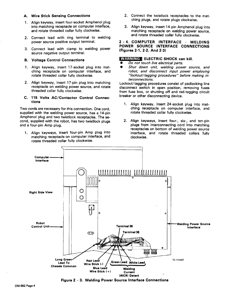
Figure 2
-
3. Welding Power Source Interface Connections
OM-882 Page 4