5. equipment connection diagram – Miller Electric DS-64M Swingarc User Manual
Page 16
OM-1588 Page 12
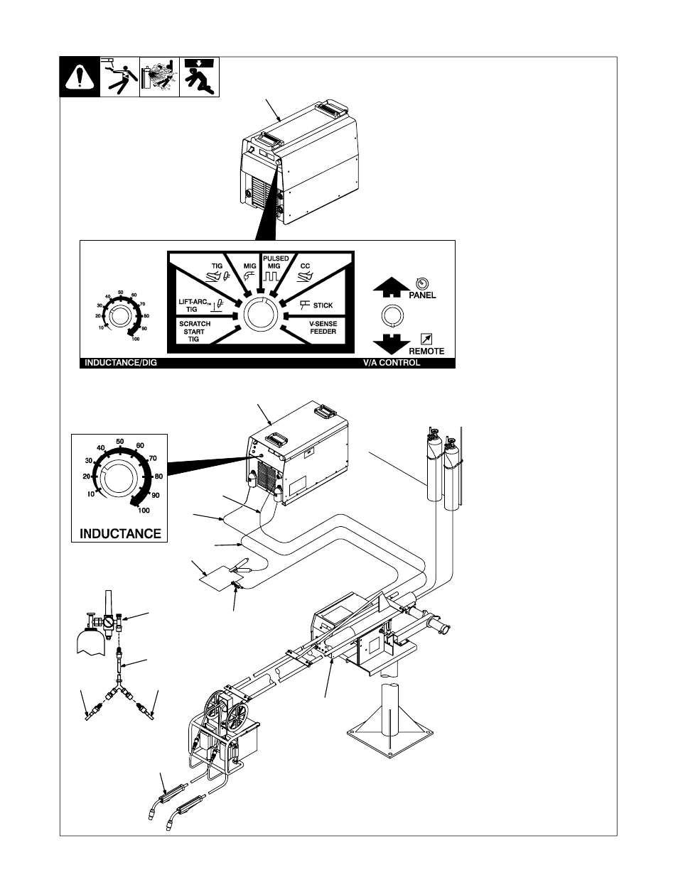
4-5. Equipment Connection Diagram
ST-801 806 / Ref. ST-175 086 / Ref. ST-180 311-B
1
300/400 Ampere Model
CC/CV Inverter Welding
Power Source
.
Use settings shown for both
pulse MIG welding and MIG
welding.
2
450 Ampere Model CV
Inverter Welding Power
Source
3
14-Pin Cord
4
Positive (+) Weld Cable
5
Negative (−) Weld Cable
Be sure weld cables are sized prop-
erly for peak amperage if pulse
welding (see welding power source
Owner’s Manual).
6
Workpiece
7
Voltage Sensing Lead
(Optional Use)
8
Gun
Be sure gun is rated for peak am-
perage if pulse welding. Install ac-
cording to its Owner’s Manual.
9
Wire Feeder
For connections see Section 4-7.
10 Shielding Gas Supply
11 Supplied Y Adapter
12 Gas Hose From Boom
3
4
5
6
7
8
9
2
12
12
11
10
1
See also other documents in the category Miller Electric Tools:
- OM-2241 (32 pages)
- ICE-27C (36 pages)
- Arc Welding Power Source (4 pages)
- INVISION 456 CC (44 pages)
- Welder (132 pages)
- SS-75D12 (44 pages)
- Load Bank LBP-350 (2 pages)
- OM-193 084E (36 pages)
- 750MPa (2 pages)
- APT-1000 (20 pages)
- OM-220 390F (48 pages)
- 271 (48 pages)
- Welding (32 pages)
- DC (72 pages)
- OM-129 (70 pages)
- XLi (24 pages)
- S-64 (36 pages)
- ICE-27T (36 pages)
- PipePro 304 (76 pages)
- AA40GBU (28 pages)
- D-64 (40 pages)
- Auto Arc XLT 165 (48 pages)
- 185 DX (56 pages)
- S-32S (4 pages)
- Big 40 DC/TIG 55500 A (8 pages)
- Big Blue 600D (60 pages)
- Millermatic 140 (60 pages)
- pmn (36 pages)
- LMSW Series (2 pages)
- 1250 (46 pages)
- Trailblazer Pro 350 D (8 pages)
- TS (76 pages)
- S-22P12 (28 pages)
- 602 (40 pages)
- Axcess 300 (56 pages)
- MOG-400 (40 pages)
- WC-24 (20 pages)
- Big Blue 502P (64 pages)
- Dimension 1000 (44 pages)
- DS-74DX12 (52 pages)
- 350 VS (36 pages)
- 24A (32 pages)
- GA-16C (12 pages)
- Big Blue 502D (116 pages)
- OM-229 038D (36 pages)