MITSUBISHI ELECTRIC FC810 User Manual
Page 36
MITSUBISHI ELECTRIC MOTHERBOARD DIVISION
PAGE 36 OF 45
!
"
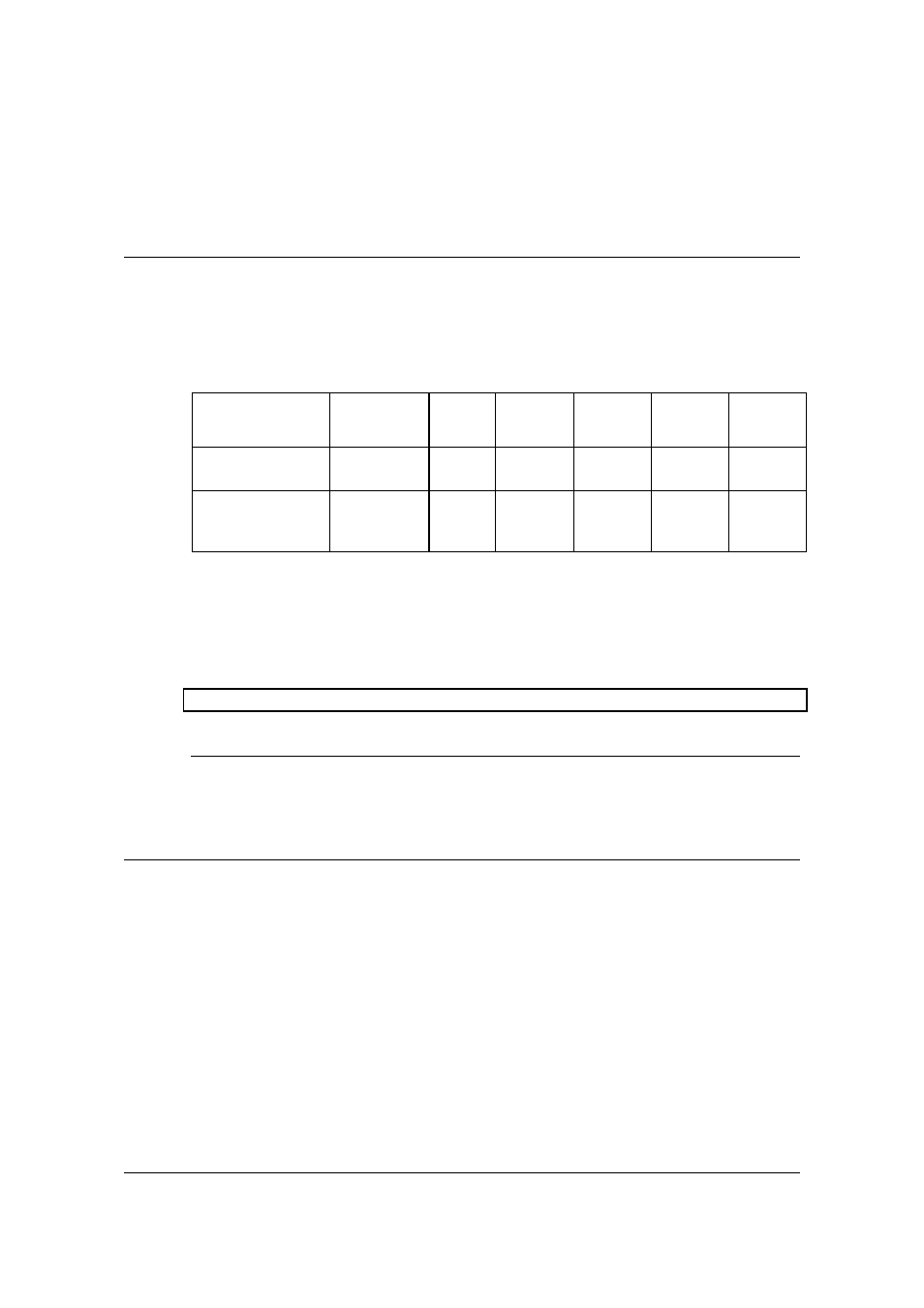
The motherboard power requirements are heavily dependent on system configuration and the
software being used. The table below can be used as a guide to the likely power supply
requirements. They are measured using a 400MHz Intel Celeron Processor and 2 memory
modules running stress test software designed to yield worst case results. They should not,
however, be regarded as maximum values.
")
*+,
)
*+,
*-.-,
*/0,
1/0,
1+,
Voltage
Tolerance
5%
5%
4%
5%
10%
10%
Maximum
Current (in above
configuration)
20mA
4.6A
1.9A
360mA
30mA
0mA
Note that these figures do not cover cards plugged into the slots.
When operating this motherboard with a power supply that does not provide a +5V
standby output, the PL8 jumpers (installation guide reference 2) must be fitted.
Advisory
Mitsubishi has found that some power supplies generate damaging voltages on their main
outputs when their +5V standby output is over-loaded.
The PCB is a four-layer design measuring W7.8” x L9.6”. It is ATX 2.01 compliant. The inner
power planes are arranged so that the ground plane is nearest the top component layer.
The PCB has a UL flammability rating of 94V-0.