Memorex DVR H264 User Manual
Page 67
Network Stand Alone DVR
Network Stand Alone DVR
Network Stand Alone DVR
Network Stand Alone DVR
Network (JPEG2000+H.264)
Network (JPEG2000+H.264)
Network (JPEG2000+H.264)
Network (JPEG2000+H.264)
66
CHAP.9 Programmer reference
2) RS232 ASCII-CODE
We qualify that the ASCII information is provided only as reference material for programmers
to aid them in using these RS-232 ASCII primitive commands for integration into user
developed software and applications
(The following table is based on 16ch DVR.)
All ASCII-Code is 1 Byte.
REC
‘R’
DOWN
‘J’
PTZ
‘T’
KLOCK
‘C’
CH5
‘5’
CH12
’@’
STOP
‘S’
LEFT
‘H’
ZOOM
‘Z’
ULOCK
‘O’
CH6
‘6’
CH13
’#’
PLAY
‘P’
RIGHT
‘K’
FRZ
‘F’
QPLAY
‘Y’
CH7
‘7’
CH14
’$’
Pause
‘A’
NEXT
‘N’
MODE
‘D’
CH1
‘1’
CH8
‘8’
CH15
’%’
SERCH
‘E’
ENTER
0x0d
PIP
‘I’
CH2
‘2’
CH9
‘9’
CH16
’^’
MENU
‘M’
-
‘<‘
SEQ
‘Q’
CH3
‘3’
CH10
’0’
UP
‘U’
+
‘>’
J.SHU
‘L’
CH4
‘4’
CH11
’!’
Jog / Shuttle
Jog / Shuttle
Jog / Shuttle
Jog / Shuttle
Please input ‘L’ command to activate J/SHUTTLE function using keyboard of PC.
Shuttle 0 degree
“&>0”[enter]
Shuttle Left 10 degree
"&<1"[enter]
Shuttle Right 10
degree
"&>1"[enter]
Shuttle Left 20 degree
"&<2"[enter]
Shuttle Right 20
degree
"&>2"[enter]
Shuttle Left 30 degree
"&<3"[enter]
Shuttle Right 30
degree
"&>3"[enter]
Shuttle Left 40 degree
"&<4"[enter]
Shuttle Right 40
degree
"&>4"[enter]
Shuttle Left 50 degree
"&<5"[enter]
Shuttle Right 50
degree
"&>5"[enter]
Shuttle Left 60 degree
"&<6"[enter]
Shuttle Right 60
degree
"&>6"[enter]
Shuttle Left 70 degree
"&<7"[enter]
Shuttle Right 70
degree
"&>7"[enter]
Shuttle Left 80 degree
"&<8"[enter]
Jog Minus
"&-"[enter]
Jog Plus
"&+"[enter]
Shuttle : After inputting a command once, it will keep performing the command until
next
command.
Jog : It makes the stage staying after one time operation by command input like
Button
operation.
CHAP. 9 Programmer reference
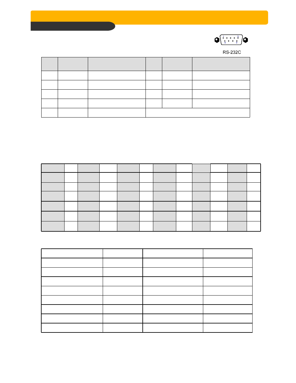
1) Connector Pin Assignment
No
Description
NO
Description
1
DCD
Data Carrier Detect
6
DSR
Data Set Ready
2
RxD
Receive data
7
RTS
RS232C: Rx/Tx data
3
TxD
Transmit data
8
CTS
RS232C: Rx/Tx data
4
DTR
Data Terminal data
9
5
GND
Signal Ground