MRV Communications TERESCOPE TS800/155 User Manual
Page 35
M R V C o m m u n i c a t i o n s , I n c . – I n s t a l l a t i o n M a n u a l
25
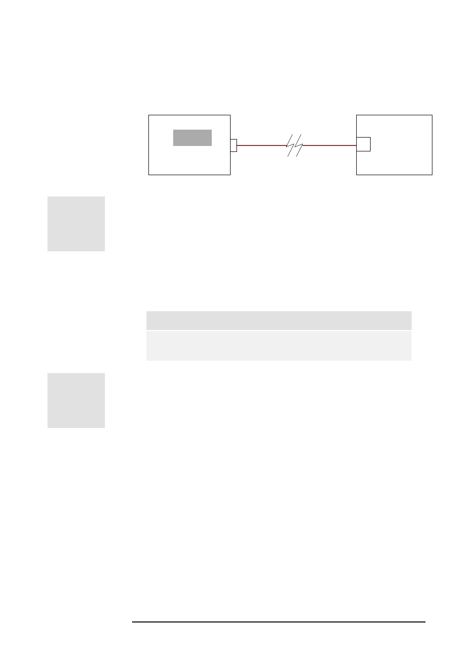
A simple power loss test can inform us about the condition of the
fibers. This test consists in measuring (with an optical power meter)
the output power at one end of the tested fiber when a fiber source is
connected at the other end. If the values are in dBm, the difference
between the input power and the output power gives the power
attenuation of the fiber (in dB).
Optical Power Meter
dBm
Peripheral
Equipment
or
Optical Source
F/O
TX
Fiber Optic
Cable
In case the above equipment is not available, a simple visual test may
be performed to locate and reject badly damaged fibers. Place a light
source at one end of the fiber and intermittently block it and observe
the light coming out of the other end. (This procedure does not
guarantee that a fiber is acceptable)
A standard 62.5
µµµµ
m fiber optic cable is characterized by an
attenuation factor of about 3 to 5 dB/km. A loss value of more
than 3 dB for runs up to 200m indicates that the fiber may be
faulty.
Note
The fiberoptic cables must be installed by a qualified person.
HANDLE THE FIBERS VERY CAREFULLY.
2. For TS700/100
Type
For connecting the Transceiver to the peripheral equipment, 2-pair
STP Category 5 cable is required (one pair for transmission, the other
for reception). This cable must be a straight one when the peripheral
has an MDI-X 100Base-TX interface and a Cross one otherwise.
For PoE (Power over Ethernet), 2 more pairs STP Category 5 cable are
required. (Use only for the Low Voltage version: TS100/A/FET/V3)
Connectors
The cable should be terminated with an RJ-45 connector at the
Transceiver end.
(
!
Figure 3.1: F/O cable test.