Back panel description – MRV Communications TERESCOPE TS800/155 User Manual
Page 14
M R V C o m m u n i c a t i o n s , I n c . – I n s t a l l a t i o n M a n u a l
4
Back Panel Description
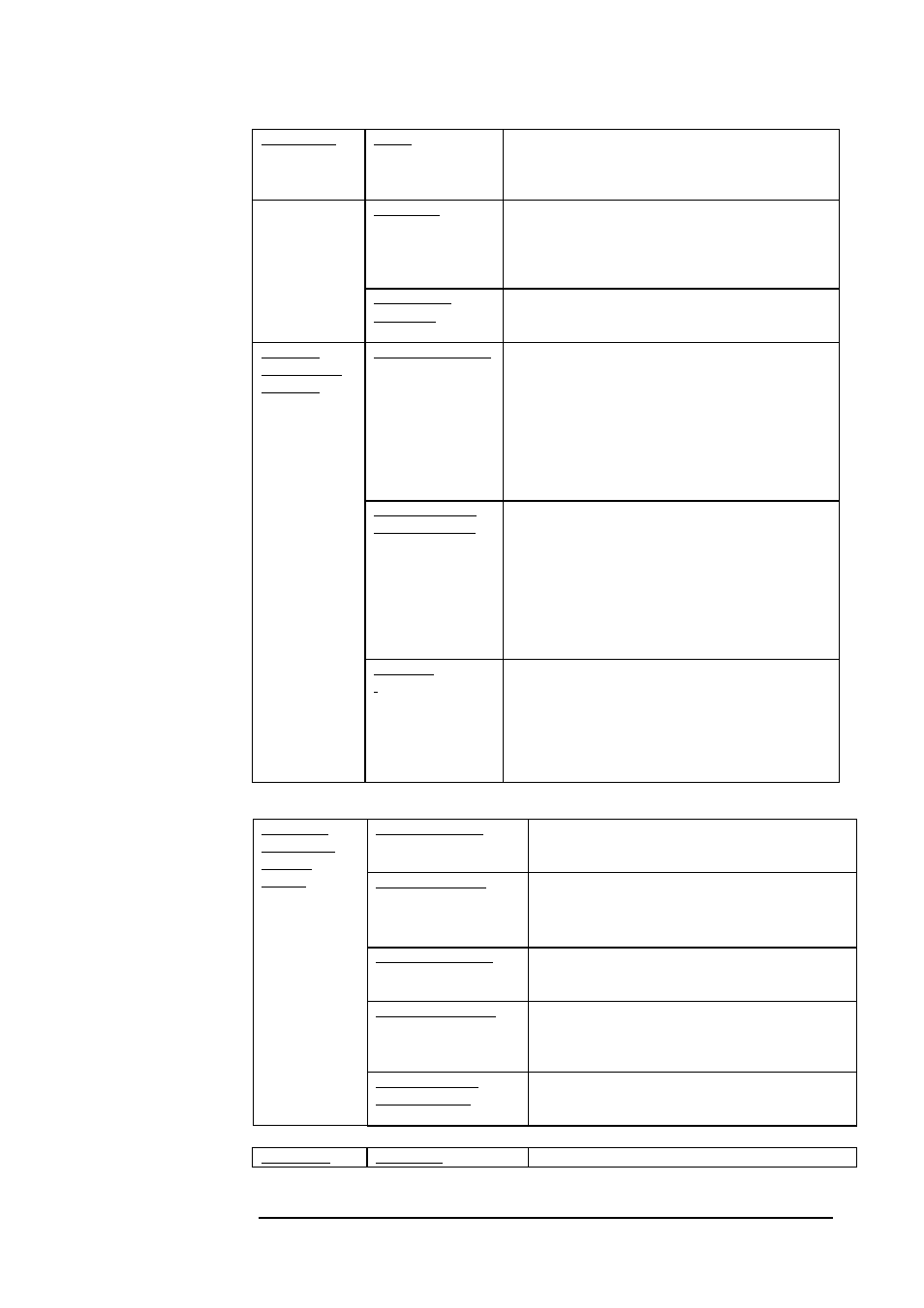
Table 2: TS700/155 Standard Model Back Panel Controls, Interfaces, and Indicators
Air RX Flag LED
Green LED indicates data received by the Airlink
receiver. Turns ON at the threshold level.
Air RX Sync LED
Yellow LED. Turns ON if the rate of the received
Data matches the Data Rate set on the Data Rate
DIP switch.
F/O RX Flag LED
Green LED indicates Data received by the Fiber
Optic receiver. Turns ON at the threshold level.
F/O RX Sync LED
Yellow LED. Turns ON if the rate of the received
Data matches the Data Rate set on the Data Rate
DIP switch.
Indicators
(7-segment
display,
LEDs)
Optical Power 7-
segment display
Digital readout indicates the Optical Power level
received by the Airlink receiver.
Alignment Telescope
For fine alignment.
Connectors
Power
Power source Terminal Block (Main or UPS)
AC power supply (100 to 240 Vac) or DC power
supply (24 to 60 Vdc)
Fiber optic
Fiber Optic interface for connection to the
peripheral equipment. The standard interface is MM
1310nm SC connector; other interfaces are available
upon request.
Management
(Optional)
Connection to 10base-T SNMP management
interface. (To be ordered separately)
Mode of Operation
(Toggles 1 and 2)
Set the Operating Mode
ALIGNMENT = Idle transmitted automatically
NORMAL = Signal received through the F/O port
is transmitted through the Airlink TX. Signal
received through the Airlink RX is transmitted
through the F/O TX.
LOOPBACK=The Data received by the F/O RX is
directly returned through the F/O TX.
IP address set up
(for Mgt. option)
(Toggle 3)
Used only with the management option. When the
Switch toggle is on OFF position, the TereScope’s
IP address is the default one (shown on the back
panel label: 10.0.0.101). To set a new IP address
please refer to the “IP address setting procedure for
TereScope management card” file in the Manuals
CD. The new IP address is valid only after the
TereScope is powered off and on.
Selectors
(DIP Switch
Toggles)
--
shown in Figure
1.3
Data Rate
(Toggles 4 and 5)
Set the transmission rate of the transceiver (internal
clock).
- Fast Ethernet: 4,5 OFF
- ATM/OC3/STM1:155 Mbps: 4,5 ON
- E3: 34.368 Mbps: 5 OFF, 4 ON
- T3: 44.736 Mbps: 4 OFF, 5 ON